Ausgabe 01_2015
The mostly applied shaft sinking method is conventional shaft sinking by drilling and blasting. Using this method, almost any shaft geometry is feasible and challenging ground conditions can be sunk through with acceptable sinking performances. Particularly mucking and hoisting operations of the sinking cycle have a relevant impact on sinking performance and offer a considerable optimization potential. Nevertheless further developments concerning sinking performance are only rarely noticeable over the last decades.At the beginning, this paper discusses parameters influencing mucking and hoisting performance. Furthermore, it is shown with assumed sinking scenarios that the selection of appropriate mucking equipment reduces mucking time significantly. The paper ends with concepts of pneumatic loading technology that offer additional options to improve sinking performance.
1 Introduction
For civil and mining construction purposes shafts provide a vertical connection from surface to an underground working area. Those shafts can be excavated either by conventional drilling and blasting or by mechanical sinking methods. In the majority of cases (roughly 70 %) conventional shaft sinking is the applied sinking method, due to its flexibility concerning shaft geometry and surrounding rock conditions. Nevertheless development respective, e. g. sinking performance of the conventional shaft sinking method is lacking over the last decades.
The process cycle of conventional shaft sinking involves drilling and blasting operation, mucking and hoisting of blasted material, installation of primary rock support and permanent shaft lining. Mainly, blastholes are drilled with special shaft jumbos or less by handheld-drills. After charging and blasting a round, gases and dust have to be ventilated out of the shaft. Subsequent mechanized muckers load the blasted rock fragments into rock kibbles. Here, several types of muckers with different operation principles and locations are used. The filled kibble is transported via mine hoist to the surface. After mucking and cleaning up the shaft bottom, primary rock support is installed as required. Shaft lining is erected either from the sinking stage or from the shaft bottom. Mucking and hoisting in shaft sinking can account for over 50 % of cycle time, particularly at large diameters and long rounds. Hence, this process step provides the opportunity to improve sinking performance.
Firstly, basic parameters are presented that influence mucking and hosting performance. Beside different mode of operating of the respecting equipment, mucking capacity depends on size of rock fragmentation and dimensions of blasting round. The following shaft mucker types are considered in this paper: Cactus Grab, Cryderman Shaft Mucker and Overshot Loader.
In the following the optimal selection of these shaft muckers will be illustrated in depending of different frame conditions. Finally in the last section of this paper, additional approaches regarding pneumatic loading technology to increase shaft sinking performance will be discussed.
2 Parameters influencing mucking and hoisting performance
The time for mucking and hoisting excavated material from one round is defined by the average mucking performance and the performance of the hoisting equipment. While the mucking performance is almost independent of the sinking progress, the hoisting performance decreases with increasing depth, assuming a constant kibble size. When hoisting performance is the limiting factor of mucking and hoisting operation, this is called the critical hoisting depth. Before starting the actual mucking and hoisting operation, the blasted rock has to be prepared for mucking operation and mucking equipment has be brought into position.
2.1 Preparatory Work
Preparation before mucking and hoisting operation comprises leveling of the shaft bottom and boulder breaking. The duration of these preparatory steps varies, depending on the used blasting and mucking technique. When required pre-work at the shaft bottom is completed, the mucking equipment can be brought into position.
A plain working surface provides the basis for efficient and more safety working operation at the shaft bottom. The manual leveling work begins after the first inspection to assess the blasting results. An average leveling capacity of about 1.5 m2/min can be expected. Higher requirements concerning the evenness of the working surface extend the leveling process.
For example, a rough working surface impedes a smooth-running mucking operation using a crawler mounted overshot loader that operates with a front-mounted shovel. Due to its compact construction and jerky mucking movement, especially overshot loaders need an even shaft bottom. Furthermore, a secure kibble base area on the shaft bottom during mucking operation is absolutely necessary. The sinking crew has to prepare a slightly lower position for the incoming kibble. This working step has to be considered during the entire mucking and hoisting operation.
Sometimes the blasted rock contains components of large size fragmentation, so called boulders. These oversize rocks have to be broken into a loadable fragmentation size. Depending on the bucket size of the mucking equipment, the maximum loadable rock size varies. Using a Cryderman Shaft Mucker with a generally smaller bucket compared to a Cactus Grab, a relatively higher amount of boulders in the muck can be expected. Boulder breaking is done mechanically with drills or by blasting. Blasting is very time-consuming, as the common shaft sinking cycle is interrupted by additional blasting and ventilation (1).
The mucking equipment listed above differs regarding the way to bring it into position. An overshot loader is hoisted from the surface down to the shaft bottom. In exceptional cases, the overshot loader can be stored on the sinking stage. With regard to total time demand, both hoisting and lashing of the overshot loader has to be considered. The hoisting time from surface increases with sinking progress.
A Cryderman Shaft Mucker with limited telescopic boom is mounted on the sinking stage. Thus, a Cryderman Shaft Mucker is brought into position by lowering the sinking stage (2). Based on a safety distance of roughly 30 m between shaft bottom and sinking stage to prevent blasting damages and a lowering velocity of the sinking stage of 1 m/min, it takes about 30 min to set up a Cryderman for mucking. Concerning long rounds and large shaft diameters, the Cryderman’s telescopic boom is not long enough to load a complete round, without additional lowering of the sinking stage.
Mucking operation using Cactus Grabs is almost independent of the position of the sinking stage, because the vertical movement is accomplished by a rope winch that is mounted under the sinking stage (3).
2.2 Mucking Operation
Mechanical mucking operation in shaft sinking consists of three consecutive parts: mucking with maximum capacity, mucking with reduced capacity and final cleaning. The performance of mechanical shaft muckers decreases, when their digging units hit solid rock and the filling degree of the bucket is not optimal anymore. That means the less blasted material on the shaft bottom the less mucking performance due to a reduced filling factor of the bucket. The digging depth of the bucket defines when mucking with reduced capacity sets in. When finally mechanical mucking equipment is getting less efficient than manual mucking by the shaft crew, this indicates the beginning of the final mucking part: cleaning the shaft bottom.
Accordingly, the capacities of each part of mucking operation and their relative shares add up to the average mucking capacity. Different blasting round dimensions and mucking equipment parameters – e. g. bucket size and digging principle – lead to different amounts of blasted rock that can be mucked with appropriate capacity.
To calculate the maximum capacity of the mucking equipment, the following formula may be used:
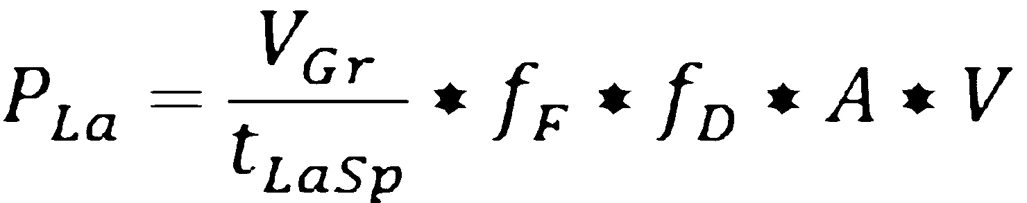
With:
PLa = mucking capacity [m3/min]
VGr = bucket volume [m3]
tLaSp = mucking cycle time [min]
fF = fill factor
fD = factor for equipment dimension
A = capacity utilization
V = availability
The length of the mucking cycle time, composed of the process steps digging, swinging (or driving backwards) and lifting, discharging, swinging (or driving forward) and lowering is determined by the general working principle of the mucking equipment. Furthermore, major factors affecting the muck cycle time are properties of the blasted muck and operator skills.
When mean fragmentation size is getting larger, digging time increases due to higher digging resistance of the coarse material (4). A comparison of digging times between cactus grab and overshot loader clarifies that besides mean fragmentation size, bucket configuration and digging movements also effect the digging time. The pointed grab shells of a cactus grab hit vertically on the blasted material and intrude smoothly into the muck, almost independent of fragmentation size. In contrast to that, coarse material restrains a smooth filling of the front shovel of an overshot loader when driving forward. Hence, the digging time of an overshot loader increases considerably, in case coarse material has to be loaded.
Additional impact on the muck cycle time has the selection of equipment dimensions specifically bucket dimensions. Larger equipment size leads to slower movement and larger bucket size results in increasing digging resistance (5). These parameters again lead to longer mucking time. They are considered in the formula for mucking capacity with an empirical factor for equipment dimension (fD). Beside operator skill, the bucket fill factor (fF) of mucking equipment is mainly dependent the distribution of fragmentation size. Empirical investigations show that low fill factors are attended by increasing mean fragmentation size (6).
The following diagrams show the development of the maximum mucking performances of the mentioned equipment affected by both, mean fragmentation size and commonly used bucket sizes.
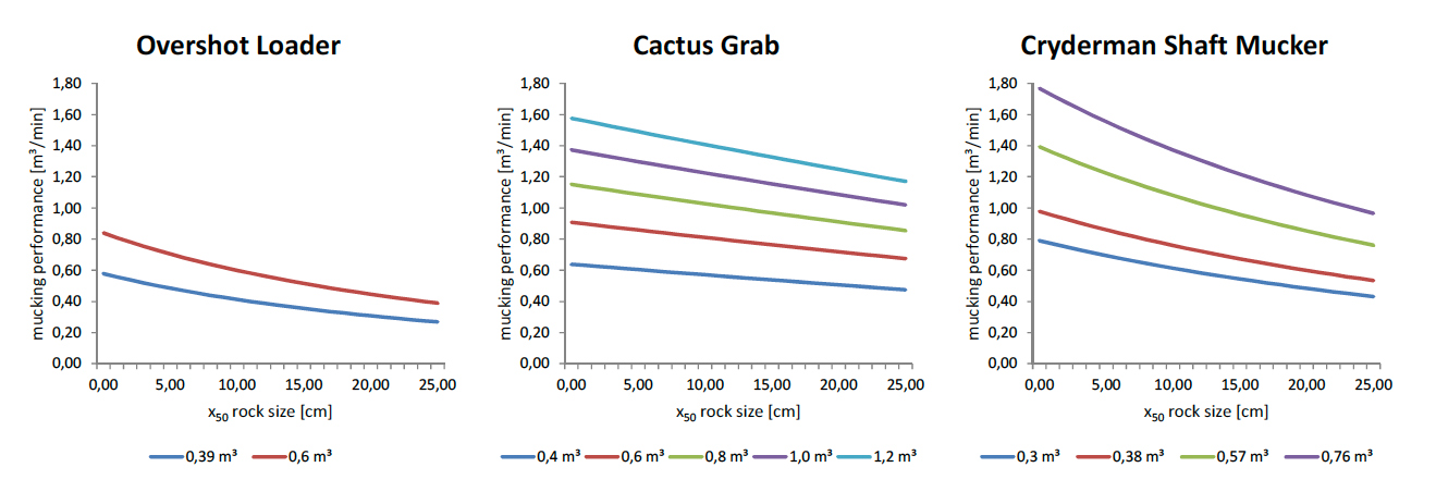
Fig. 1. Mucking performance of selected equipment.
Bild 1. Entwicklung der Ladeleistung ausgewählter Ladegeräte bei vollem Eingriff in das Haufwerk
2.3 Hoisting Operation
To calculate the cycle time of the sinking process, mucking and hoisting operation have both to be considered. Independent of mucking performance, hoisting performance (kibbles/h) is determined by hoisting cycle time, kibble size and number of used kibbles. The hoisting cycle time consists of lashing on the filled kibble to the hoisting rope, hoisting to surface (filled), kibble discharging, hoisting down to shaft bottom (empty) and lashing of the lowered kibble. The hoisting time, without lashing and discharging, is affected by effective depth of the shaft and hoisting velocity. In the vicinity of sinking stage and shaft headframe slow hoisting velocities have to be considered. According to “Technische Anforderungen an Schacht- und Schrägförderanlagen” (TAS), the maximum hoisting velocity for shaft sinking operation is 12 m/s in normal mode and 1 m/s during slow hoisting (7).
In great depth, loading capacity of the hoisting rope limits the kibble size. Generally, kibble sizes of 3 – 7 m3 are common. In particular cases, mucking equipment determines the maximum kibble size. So is the discharge height of an overshot loader about 1.9 m, accordingly the kibble dimension has to be adapted to the mucking equipment’s construction (8).
An increasing number of kibbles improve hoisting performance. A double drum hoisting machine enables shaft sinking with three-kibble-operation, which represents the maximum number of kibbles. The kibble handling on the shaft bottom is done by the sinking crew. They push the empty kibble, coming from the surface into the provided slot in the blasted muck. Then, the snap hook is lashed off from the empty kibble and is connected to the kibble standing already filled on the shaft bottom. The diagonal pull of the hoisting rope generates an oscillating kibble movement that has to be slowed down manually by the sinking crew. At the same time, the third kibble is discharged at the surface in a chute on the headframe. Generally, discharge the kibble needs more time than lashing work at the shaft bottom.
Figure 2 illustrates the lower capacity of a two-kibble hoisting system compared to a three-kibble-system. In this example, the critical hoisting depth for two-kibble-operation is roughly 780 m, considering a minimum hoisting performance of 6.5 kibbles/h. For greater depths, it is reasonable to increase the hoisting performance by using the three-kibble-system. The critical depth of the three-kibble-system is about 2670 m. Below this depth, the mucking equipment cannot reach its maximum performance due to further decreasing hoisting performance.
3 Mucking Eqiupment Selection
The selection of appropriate mucking equipment reduces the time needed for mucking an entire blasting round and thus enhances sinking performance. Table 1 describes three assumed shaft sinking scenarios, to compare overshot loader, Cryderman Shaft Mucker and Cactus Grab regarding their operating performance. The sinking scenarios differ concerning blasting round length, shaft diameter, depth and rock properties. The selected bucket sizes of each mucking equipment are adapted to the respective operating condition. For this comparison, it is assumed that hoisting performance is always higher than maximum mucking capacity. The calculated data regarding mucking time and capacity are based on a proprietary performance and cost model for conventional shaft sinking.
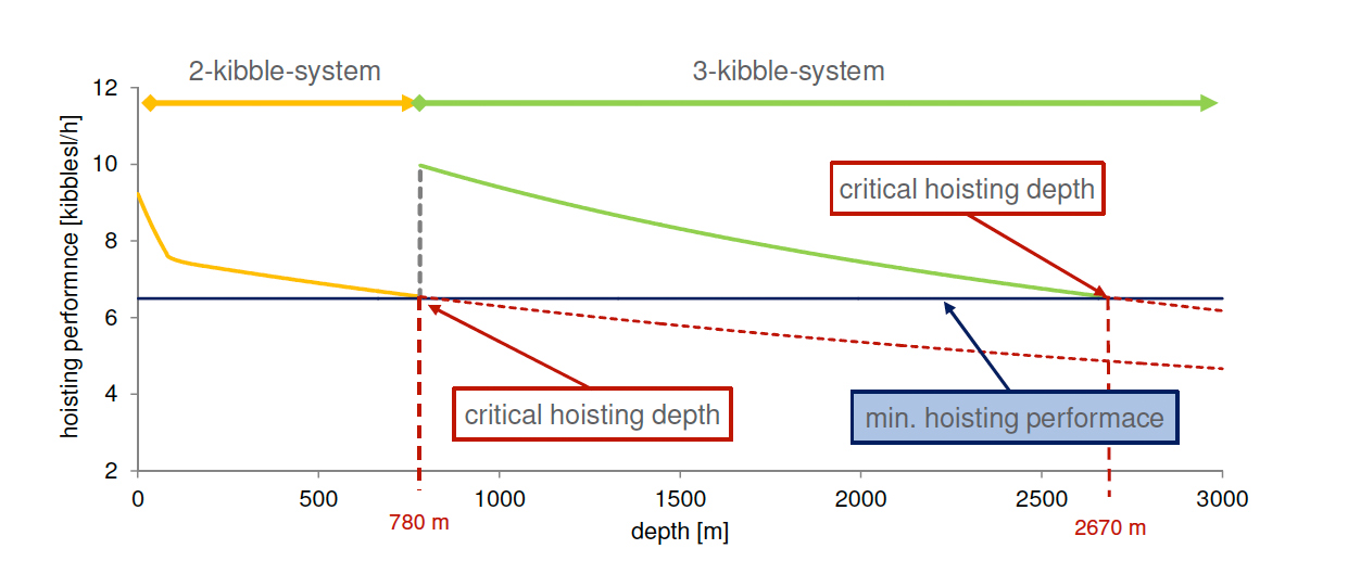
Fig. 2. Interaction of mucking and hoisting performance affected by depth and hoisting system
Bild 2. Lade- und Förderleistung in Abhängigkeit von Teufe und Kübelanzahl
The first scenario is characterized by a short blasting round and finely grained rock fragmentation. This makes an overshot loader the equipment of choice, which is proven by the calculated mucking time (figure 3). Finely grained material enables a smooth filling of the lowered front shovel and a mucking cycle takes around 35 s. The available space (8.5 m diameter) is sufficient for mucking movement of an overshot loader.
Furthermore, short blasting rounds lead to relatively higher proportion of cleaning the shaft bottom in comparison to long blasting rounds. Here, the low digging depth of an overshot loader is of advantage and only a small amount of blasted material has to be mucked manually by the sinking crew. The histogram in figure 3 highlights that the overshot loader can muck at maximum capacity for a longer time than the other equipment. Thus, the comparatively lower mucking capacity is balanced. The longer time needed to bring the overshot loader into position (hoisting from surface) is not relevant for low depths. The low investment costs are a further advantage of the overshot loader. This fact is important for low budget shaft sinking projects.
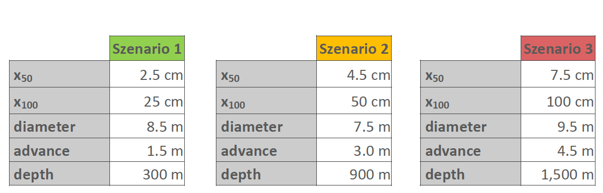
Table 1. Shaft sinking scenarios for comparison
of the mucking equipment
Tabelle 1: Teufszenarien für die Auswahl von Ladegeräten.
Based on the model calculation, the Cryderman Shaft Mucker is the optimal mucking equipment for sinking scenario 2. The frame conditions comprise moderate length of blasting round, smaller shaft diameter comparing to scenario 1 and medium grained fragmentation size. Due to the short mucking cycle of about 25 s, the Cryderman Shaft Mucker accomplishes a high-capacity mucking operation. As a result of the medium sized bucket, the time needed for mucking with reduced capacity and shaft cleaning is smaller compared to a Cactus Grab. Present rock fragmentation size is suitable for the selected bucket size and additional boulder breaking would not be required. Despite the long time to bring the Cryderman into position due to slow sinking velocity of the sinking stage, it achieves high mucking performance and requires low effort for shaft cleaning.
By means of long blasting rounds, a high sinking performance can be reached, also for wide shaft diameters. A high-capacity Cactus Grab using a 1.2 m3 bucket achieves under these frame conditions the highest average mucking performance considering the preparatory time. Moreover, the large scale geometry of the blasting round requires mucking equipment with an appropriate vertical and horizontal operating reach. The widely opened grab shells of the Cactus Grab provide an efficient mucking of coarse material. The histogram in figure 5 illustrates that prior boulder breaking delays the start of mucking operation for an Overshot Loader or a Cryderman Shaft Mucker. No further boulder breaking is needed, when a Cactus Grab is used. When using a Cryderman Shaft Mucker, the sinking stage has to be lowered twice for mucking the entire round. Thus, the mucking operation is interrupted and the average mucking performance of a Cryderman Shaft Mucker with limited reach is lower compared to the Cactus Grab. Scenario 3 represents a capital intense shaft sinking project. The overall sinking costs are mainly driven by costs of consumables and other operations. Expenditures for expensive mucking equipment like a Cactus Grab have only minor impact on total sinking costs.
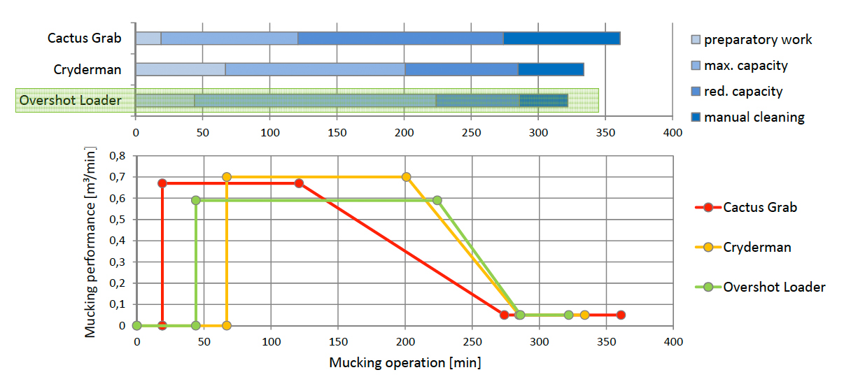
Fig. 3. Time for mucking operation (scenario 1)
Bild 3. Zeitaufwand für Ladearbeit (Teufszenario 1)
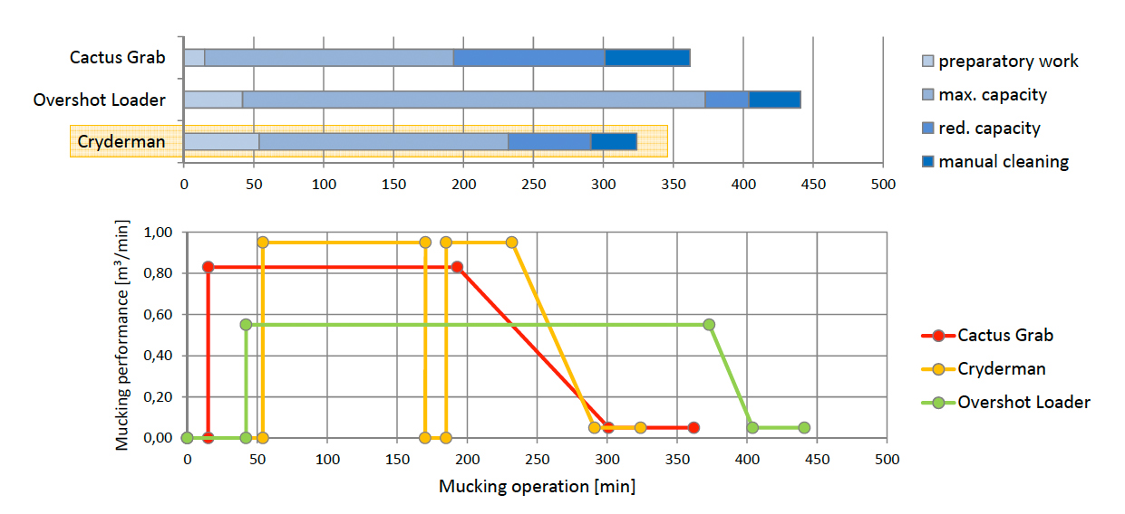
Fig. 4. Time for mucking operation (scenario 2)
Bild 4. Zeitaufwand für Ladearbeit (Teufszenario 2)
4 Further Optimization Approaches
To increase sinking performance while using conventional equipment, partly parallel implementation of selected process steps of the shaft sinking cycle is feasible. Safety regulations and process steps that have to be extended in a sequence are often obstacles for running several processes in parallel. Installation of primary rock support and final shaft lining are process steps that can take place on different levels of the sinking stage, simultaneous to drilling and mucking operations on the shaft bottom, as long as stability of the surrounding rock allows for a delayed installation. However, after exposing the unsupported shaft wall, commonly mucking and hoisting operations have to be interrupted during the installation of primary rock support, e. g. rock bolts and wire mesh. Depending on the used mucking and hoisting equipment, appropriate space and manpower are required, thus avoiding the installation of primary rock support in parallel to mucking operation.
Certainly, increasing the mucking capacity by using even larger bucket sizes is an obvious option. However, more stable construction components have to be provided, which increases all in all equipment costs, weight and dimensions.
Furthermore, state of the art hoisting technology (even when using three-kibble-system) is limiting the maximum mucking performance in great depth due to decreasing hoisting performance. Accordingly, to increase maximum mucking capacity of conventional equipment makes sense only for low depth shaft sinking projects. In contrast to that hoisting performance is higher than mucking with reduced capacity and even more so for cleaning the shaft bottom. The potential of optimization of these mucking parts is a significant opportunity, since hoisting performance in great depths is not a limiting factor anymore.
Besides selecting appropriate and high-capacity mucking equipment, pneumatic suction technology provides an alternative to increase sinking performance and additionally improves occupational safety. Finely grained rock that remains at the shaft bottom after mechanical mucking can be loaded into a special pneumatic kibble with a suction device. Pneumatic cleaning of the shaft bottom will reduce time and manpower needed in comparison to conventional cleaning operation. Model calculations show that the application of pneumatic suction technology for shaft bottom cleaning leads to higher total sinking performance of about 5 – 8 %.
A further concept comprises the relocation of kibble loading from the shaft bottom to a fixed loading facility on the sinking stage. This avoids complicated and partly dangerous handling of large rock kibbles. In addition, otherwise busy manpower is available for further work, e. g. installation of primary rock support. Raising the location of kibble loading leads to an improved hoisting performance, due to the reduction of slow hoisting parts and the option to use larger kibble sizes.
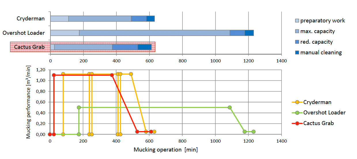
Fig. 5. Time for mucking operation (scenario 3)
Bild 5. Zeitaufwand für Ladearbeit (Teufszenario 3)
This modification will need a vertical intermediate conveyor, transporting the rock from the shaft bottom up to a bunker installed on the sinking stage. Additionally, the bunker serves as a buffer for deviation of the mucking and hoisting performance. The kibble is then loaded via bunker removal. A pneumatic suction system can provide mucking on the shaft bottom and vertical conveying to the intermediate bunker on the sinking stage. According to the model calculation, pneumatic mucking and conveying can significantly improve sinking performance for low particle sized muck.