1 Introduction
In addition to other factors, the steadily increasing depth and the increase in operating point subsidies at RAG Aktiengesell-schaft, Essen/Germany, led to greater demands on mine safety. Of prime importance was a stable ventilation. The increasing heat release by the mountains and the used extraction and conveying equipment required the development of a suitable climatization for an adequate employment of the miners. The mastery of the mine gas required corresponding developments in planning, gas drilling technology and gas extraction. The following explanations provide an overview of the main development phases in ventilation, climatization, gas control and weather monitoring. You make no claim to completeness.
2 Review of key development phases in mine ventilation
2.1 Phase 1: 1969 to 1984
In the 1960s and 1970s air circuit calculations were executed by central computers. In the mid-1970s the standardization of ventilation structures began.
In the 1970s, booster fans with a drive power of 15 kW were common. Deduster fans had a drive power of 24 kW. Two consecutive connected fans were usual.
The total return-air flow from the face zone constituted about 20 m3/s.
Production faces were mainly based on the simple U-layout.
2.2 Phase 2: 1985 to 2000
Since the mid-1990s the ventilation-efficient workplace (WTAP – Wettertechnischer Arbeitsplatz) was introduced. Since the mid-1980s revised standards for ventilation structures, ducting and fans were presented. RAG introduces ventilation regulations, e. g., various operating recommendations and instructions.
Main fans with two active changeover sections and units with fan blades that can be adjusted on the move were introduced. Further increase in air-duct diameter took place.
Significant increase in total return-air flow from the face zone from 25 m3/s to 45 m3/s happened.
The proportion of coal faces operating the U-layout fell to about 20 % as Y-layout rose strongly.
2.3 Phase 3: 2001 to 2015
The standardised planning process (GTP – Geometrisch Techni-sches Planungssystem) includes:
- ventilation network planning;
- positioning of ventilation equipment;
- main ventilation report; and
- fire buoyancy calculation.
Deduster fans got more powerful. Counter rotating fans with a drive power of 2 x 75 kW were common.
An ongoing increase in the total return-air flow from the face zone to almost 50 m3/s took place. Figure 1 shows the time-dependent total airflow from the face zone, as previously described.
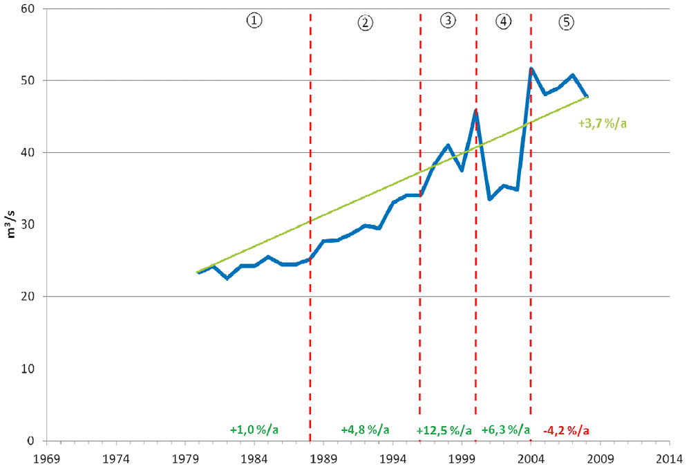
Fig. 1. Trends in total airflow from the face zone. // Bild 1. Entwicklung des Gesamtwetterstroms aus dem Abbau.
The proportion of faces with Y-layout increased to around 70 % and H-layout about 20 %.
Advance working (Figure 2) relating to mine ventilation exists when the air pressure gradient – referring to the goaf – is directed to the starting area of the longwall face on the return air side.
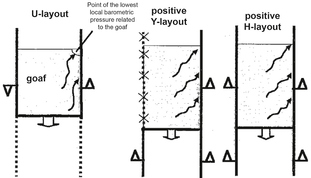
Fig. 2. Types of ventilation layout used for advancing working. // Bild 2. Zuschnittsformen im wettertechnischen Vorbau.
If presupposed a relatively dense roadside pack, not a sudden influx but a steady influx of gas emission from the adjacent seam as well as the heat from the goaf in the air along the roadside pack cropped up. From economic point of view a high performance longwall operation with stronger gas emission or higher heat load could only be operated by advance working relating to mine ventilation and a positive Y- or H-layout. With such layouts a longwall air flow was refreshed by a fresh and unencumbered air flow.
Figure 3 shows the time-dependent proportion of different coal-face ventilation layouts.
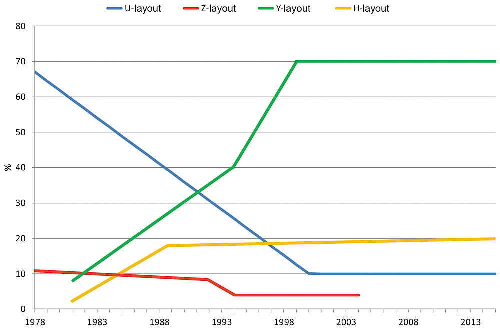
Fig. 3. Trends in the use of different coal-face ventilation layouts. // Bild 3. Anteil der Abbaubetriebe mit verschiedenen wettertechnischen Zuschnitten.
Figure 4 shows main fan installations with two active changeover sections.
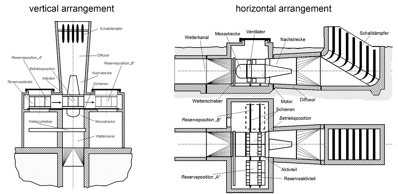
Fig. 4. Main fan system with two active changeover sections. // Bild 4. Hauptgrubenventilatoren mit zwei Wechselaktivteilen.
The active changeover sections were equipped with a chassis and a hoist for the lateral movement. One active component stands in the operating position, and the active component of the reserve is located in the reserve position “A”. In case of need the active component can be moved from its operating position to the reserve position “B” and the active component of the reserve can be moved into its place in the operating position. A change of the active components must be done in less than 20 min.
3 Review of key development phases in mine climatization
3.1 Phase 1: 1969 to 1984
This period is affected by basic research into climatization systems for coal mines. Collective wage agreement, North Rhine-Westphalia Mining Ordinance and Federal Mine Climate Ordinance aimed at regulating climate-related restrictions to the daily working time.
The total cooling capacity per mining operation increased to approximately 1,700 kW and the specific cooling capacity to 3,300 kW/M tv.F./a. Decentralized refrigeration machines up to 380 kW were in operation.
High-pressure/low-pressure heat exchangers for cooling distribution and long-haul and long-distance coolers for on-site air conditioning were developed (Figure 5).
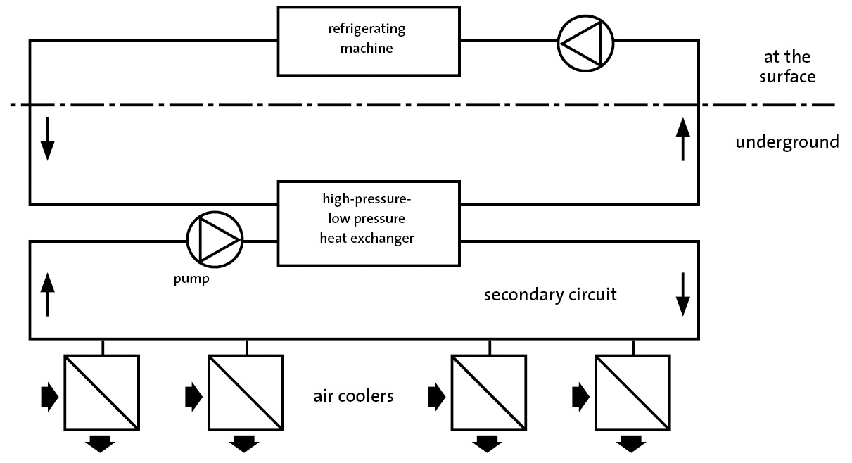
Fig. 5. Twin-circuit coolant transport with high pressure/low pressure heat exchanger.
Bild 5. Zweikreis-Kälteträgertransportsystem mit Hochdruck/Niederdruck-Wärmetauscher.
The surface installed refrigerator set the air conditioning in the mining sector to the problem, to master the enormous hydrostatic pressure differences between the above ground and underground water circuits. The system was divided into two water circuits. The primary circuit was coming from above ground and flew back there. The underground water circulation to and from the working units was called secondary circuit. Both water circuits had a thermic connection at the high pressure/low pressure heat exchanger. Such an apparatus had the disadvantage of a temperature change in the heat exchanger of about 4 K.
The further development of cooling pipes with internal insulation instead of the still used pipes with external insulation was driven forward.
3.2 Phase 2: 1985 to 2000
In this phase an RAG standard for weather coolers was developed.
An increase in the total cooling capacity per mining operation to approximately 5,200 kW and the specific cooling capacity to 4,250 kW/M tv.F./a was achieved by the year 2000.
It managed the commissioning of weather coolers up to 1,000 kW. The use of ice machines for decentralized refrigeration in low-power mining operations became necessary. Three-chamber feeders for cooling distribution were used as further developments of the high-pressure/low-pressure heat exchangers (Figure 6).

Fig. 6. Surface cooling plant with triple-chamber pipe feeder. // Bild 6. Übertägige Kälteanlage mit Dreikammerrohraufgeber.
The triple-chamber pipe feeder was used for the first time in 1984 for air conditioning purposes in mining on the Ruhr. It existed of three exchanger tubes, where alternatively on the one hand high pressure water was channeled into a low-pressure circuit and on the other hand low pressure water into a high-pressure circuit. So cold high pressure water from the shaft pipe flow into the underground cooling water circulation and pressed warm low pressure water into the high pressure return line of the shaft. The exchanger pipes were periodically blocked at the main valves against the shaft lines respectively against the low pressure lines and the particular pressure was compensated.
Triple exchanger tubes, whose work phases ran off time-delayed, were required for the quasi-continuous flow of high pressure and low pressure water. The main valves and pressure compensation valves were operated using a control program. In those locations where cold water and warm water connected, there were minor mixtures. The temperature change in the triple-chamber pipe feeder was very low; it was only about 0.5 K.
3.3 Phase 3: 2001 to 2015
For reasons of environmental protection, the replacement of the refrigerant R-22 was necessary.
During this time interval, the total cooling capacity per mining operation increased to approximately 5,900 kW and the specific cooling capacity to 8,300 kW/M tv.F./a. Figure 7 shows the time-dependent average total cooling capacity per face and Figure 8 shows the time-dependent specific net cooling capacity of the entire chiller.
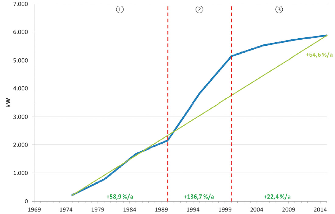
Fig. 7. Specific net cooling capacity of total refrigeration plant. // Bild 7. Durchschnittliche Gesamtkälteleistung je Abbaueinheit.
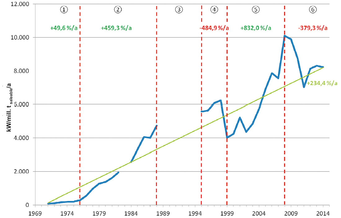
Fig. 8. Trends in total airflow from the face zone. // Bild 8. Spezifische Nettokälteleistungen der gesamten Kältemaschinen.
The most powerful cold water machine at RAG, with a cooling capacity of 20 MW, was put into operation for the climatization of plough faces at deep working levels.
Air coolers (Figure 9) were heat exchangers, in which warm air was cooled by contact with a cold surface, while the cold water supplied in closed circuits picked up the heat. The cooling pipes were made of copper. In air coolers the cold water mainly ran in cross counter current direction to the air.
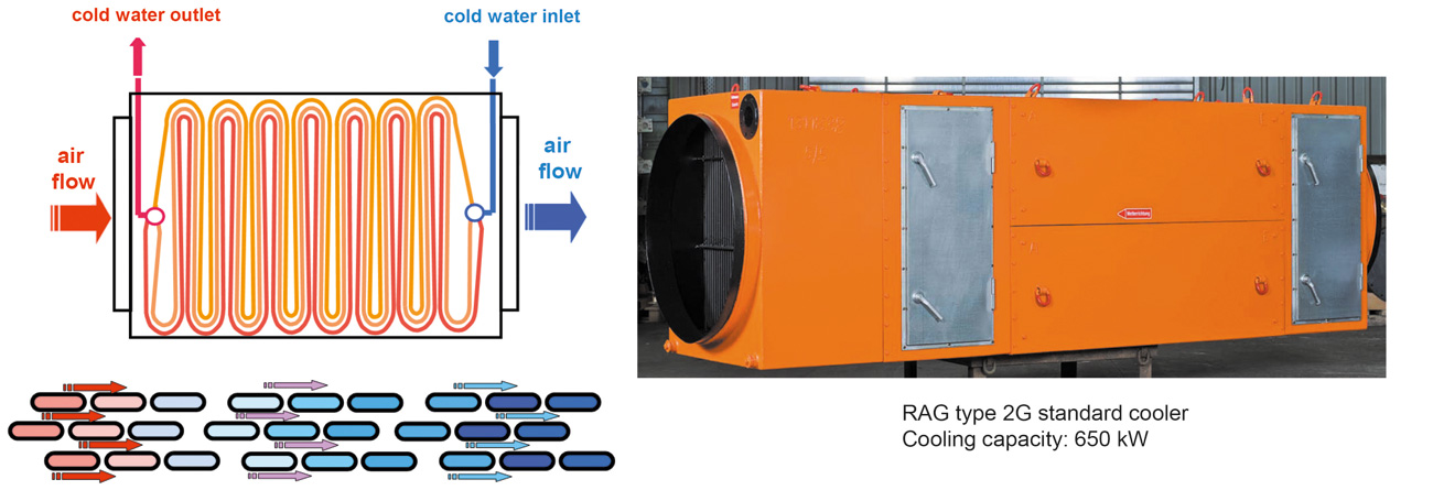
Fig. 9. Modern heat-exchanger element. // Bild 9. Wärmetauscherelement moderner Bauart.
The modern straight-tube heat exchanger omitted the heat deflectors which were used till then. From several aligned tube coils straight-tube heat exchanger plates were built. Such air coolers with large inspection hatches have been made since 1986.
4 Review of key development phases in mine climatization
4.1 Phase 1: 1969 to 1985
Everywhere the air in the free cross-section of mine workings must contain less than 1 % of CH4. Exceptions were only allowed at some working spots. There the gas concentrations could be allowed up to 1.5 %. Where higher gas inflow was estimated, advance working relating to air ventilation had to be applied to homogenize the gas emission from the adjacent seam. Exceptions were not allowed for the unfavourable retreat mining operations relating to gas emission.
The gas content is determined as the gas volume in relation to the mass of coal in m3/t. The gas content which can be released underground is the so called desorbable gas content. The difference of both is the gas content which remains in the coal.
For the development of calculation programs for PCs the following items were needed:
- determination of the gas content in the worked seam and in the accompanying seams;
- existing pipe line network to suck off the gas emission from the adjacent seams;
- capacity of the gas drainage plant;
- plan of drilling;
- requirements of air flow; and
- projected roadway cross-sections and face cross-sections.
The calculation of the gas emission for the accompanying seams is based on hypothetical gas emission spaces. That means above and below a mining work a space was defined where the stored gas could be released. This excavation-damaged zone was built by the influence of winning.
For controlling gas emission, boreholes were drilled into the worked seam and into the surrounding strata. CH4 drainage from the roof and from the floor happened by boreholes oblique to the bed. These boreholes were usually 30 to 60 m long, they were approximately 70 to 90 centesimal degrees inclined and they had a diameter between 50 and 115 mm. The distance to each other borehole was between 10 and 50 m dependent on the CH4 accumulation.
For the gas emission from the worked seam inseam boreholes were made. The gas boreholes were drilled with rotating drilling machines. These drilling machines predominantly had air-powered drill motors. Occasionally in the particular performance class also hydraulic drives were inserted. The power of the hydraulic drill motors was about 25 kW.
The ejector nozzle was a pneumatic vacuum generator. But it was unfavourable because the consumption of compressed air was high and the efficiency was low. Rotary blowers were suitable for low and medium pressure gradients.
In principle the exhauster had to be regarded as a source of ignition. Therefore a protection against explosions was required both at the suction-side and at the pressure-side. CH4 exhausters were secured with flame barriers on both sides. Also fire extinguishing installations were necessary on both sides.
The consumer line was interrupted by an emergency shutdown at a CH4 concentration of less than 25 %. Methane exhausters were turned off at CH4 concentrations of less than 22 %.
In the 1970s purely mechanical devices were used. Disadvantages like dirt or high flow resistances of mechanical devices resulted in the development of extinguishing barriers with unrestricted cross sections in the tubes. The blocking and extinguishment of flame propagations was achieved by an active system of optical flame detection and an injection of extinguishing powders.
4.2 Phase 2: 1986 to 2000
Post calculations were realized during the operating phases of the mining works to feedback and to improve the forecasting of the gas emissions with the purpose to determine the real conditions.
Since the mid-1990s also hydraulic driven rotary drilling rigs were applied systematically to make boreholes oblique to the bed.
4.3 Phase 3: 2001 to 2015
Research into gas emission from the working seam demonstrated the following: At high face output the dwell time of the coal at the longwall was shorter and the desorbed amount of the gas content was lower than those longwalls with low face output. Therefore the gas flow rose less than proportional when the face output got higher or respectively when the face length got longer.
The gas content of the coal could be very different even if the coal type was the same and the seam was the same. Figure 10 shows the changing of the gas contents inside of one working panel. The reasons are manifold. These can be geological faults, anticlines or synclines. Especially excavations above or under the regarded seam may have large influence on the gas content.
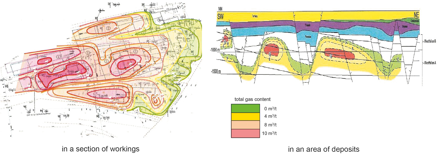
Fig. 10. Isolines indicating desorbable gas content. // Bild 10. Isolinien der desorbierbaren Gasinhalte.
The picture on the right side of figure 10 shows, that the gas content even did not depend on the depth.
In the case of a higher gas emission the CH4 concentrations at the face increased gradually towards the return air side of the face. Also the climatic loads could increase appreciably toward the return air side of the face. In such cases regulated leakage air current flow through the goaf behind the shield and parallel to the face. This leakage air current was guided directly towards the return air flow. There the leakage air current was mixed with the longwall air flow and an additional unencumbered air flow. For this purpose so-called windows were created in the roadside pack (Figure 11). The windows had to be closed again at a maximum distance of 30 to 50 m behind the face front. New windows had to be built directly behind a longwall face.
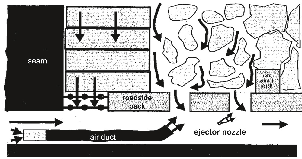
Fig. 11. Roadside pack with window system. // Bild 11. Streckenbegleitdamm mit Fenstertechnik (Grundriss).
Hydraulic drilling machines were used to produce gas wells (Figure 12). Cutter heads with carbide cutting edges and roller cutter heads were in use in the entire period. Since the mid-1970s diamond-studded drill heads and diamond drill heads were used.
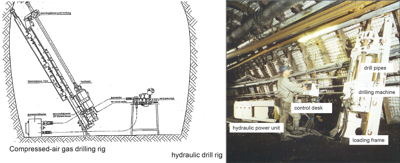
Fig. 12. Gas rig drilling at an oblique angle to the stratification. // Bild 12. Gasbohrgeräte bei bankschräger Gasbohrung.
For gas extraction itself, water ring pumps were used (Figure 13). There was a star-shaped impeller eccentrically arranged in the cylindrical housing of the fluid ring pump. The water contained in the enclosure was concentric with the housing liquid ring, which drained off the chambers during rotation. Impeller and casing did not touch while making a spark was excluded.
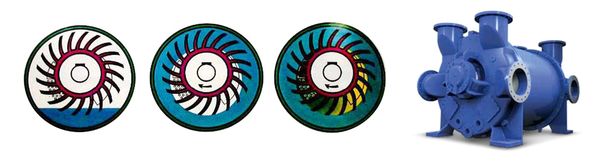
Fig. 13. Operating principle of the fluid ring pump. // Bild 13. Funktionsprinzip einer Flüssigkeitsringpumpe.
5 Representative air monitoring over the years
5.1 Year 1970: mobile gas detectors
In the early 1970s the requirement of the mining authority was the installation of fixed air speed monitors, fixed methane monitors and fixed carbon monoxide monitors and underground telemetry after appropriate handheld devices were already available.
5.2 Year 2000: stationary weather measuring equipment
An example of a flow meter for gas extraction since the year 2000: Several sensors were in one probe. These were, e. g., temperature, absolute pressure, differential pressure and low pressure. A standard gas flow could be calculated with the help of a microprocessor.
5.3 Early fire detection
In Order to identify hidden fires and small embers with CO measurement systems a new phase of early fire detection began in the 1960s. In 1978 the first version of the program for early fire detection was created and constantly advanced. CO increases which are not caused by any fire were the problem for the early detection of fire. For this reason, an automatic filtering of blasting curves with specified parameters was programmed for blasting in the mid-1980s.
To filter the CO content from diesel vehicles automatically was not practicable. If there was an increase of CO content it was necessary to distinguish whether it was a fire or the CO production of a passing diesel vehicle. Therefore about 2000 the sites were visualized in the control room where diesel vehicles were situated in the pit. Process machines of the latest generation stored the measured data.