1 Introduction
The foundation of a digital mine within the vision of Mining 4.0 is on the one hand the communication in a network of the machines amongst each other and on the other hand the autonomous operation of the equipment. A basic information needed, to reach that very goal, is the knowledge of a current position of a machine at all times (1). In the past couple of years the heavy equipment industry as well as the mining industry has framed the necessity for a precise localisation system for indoor environments. According to a research report on the “Global Indoor Location Market Outlook 2019” the market for indoor positioning systems (IPS) is expected to rise from 597 m US$ in 2014 to around 4 bn US$ in 2019 (2). This vividly shows that not only a technical but also an economic incentive, to pursue this topic, is present.
Different IPS based on different technologies have been developed in the past. These systems differ in precision, accuracy, investment cost, scalability, robustness and safety (3). Therefore, not every technology is suitable for an underground operation. Apart from the harsh environments underground, especially the small, enclosed spaces are of a problem.
In this article, the results of the research and development activities of the Institute for Mineral Resources Machine Technology (IMR) of RWTH Aachen University for an underground positioning system will be presented. Upfront the ultra-wideband (UWB) radio technology will be described as one of the most promising technologies in this application. Three different real use cases, in which the suitability was proved, will be revealed. Furthermore, a novel approach to improve the system, the so-called sensor fusion, will be pointed out. In this approach, the information gathered by the UWB system together with other sensor systems such as inertial navigation (INS) can be fused. The development of such a system is currently being carried out in the project “-Real-Time Mining” by means of financing of the EU. Further development will be carried out in the scope of the SIMS project, which also receives EU funding. Lastly, another publicly funded research project, the EMD project together with the GTA Maschinensysteme GmbH, Hamminkeln/Germany, will be illustrated.
2 Ultra-Wideband Radio Technology (UWB)
2.1 Physical basis
UWB is best suited for short-range radio transmissions. Heinrich Hertz first generated the kind of wave formation as used by UWB in 1887. The following years, however, developments went into a different direction and focussed on narrowband radio systems. The reason for this is that narrowband radio systems are easier to implement regarding technological requirements. Further developments for broadband radio systems in the 1990ies as well as the decision of the “Federal Communication Commission” of the USA to open up the range of 3.1 GHz to 10.6 GHz for UWB systems for public use, gave vantage again to the UWB technology (4, 5, 6).
A very characteristic feature of UWB is, as the name suggests, the use of a very broad frequency spectrum. Very short impulses using spectra from 500 MHz up to several GHz are being transmitted. The growing bandwidth is accompanied by an equally increasing amount of data being transmittable. At the same time, the power spectral density is decreasing. The total transmission power for the frequency range between 3.1 GHz and 10.6 GHz is limited to 1 mW. For this reason, other systems, e. g. WLAN, Bluetooth, etc., operating in the same frequency range will not be disturbed (6, 7).
Among the advantages, the UWB system has over other comparable radio systems for the use as localisation system, are the simple hardware, little influence regarding interferences when used with other radio systems, and the robustness towards multipath effects (8, 9, 10). When talking about the term multipath effect, it describes the physical phenomena of waves being reflected of walls when transmitting in enclosed spaces. On the receiving side, several timely dislocated pulses arrive, though originally only one pulse was sent out. With regular radio systems, these overlapping waves cause distortions and interferences. This in turn leads to a diminished data transmission capacity or even completely faulty signal. This effect can mainly be observed in industrial environments, where a lot of steel and concrete structures exist. UWB on the other hand has a relative immunity for this effect. For it uses very short pulses, the first signal is easy to identify and can be used i. e. for a time of flight measurement.
Next to the robust and efficient data transmission, the UWB system can be used for localisation purposes (11). Mobile equipment i. e. can be localised safely in harsh environments, e. g., in underground mines. Tests showed, that the localisation and data transmission for distances up to 200 m can be carried out without troubles in such environments.
2.2 Localisation using UWB
Localisation using UWB can be carried out by use of several UWB modules. In this application the position of a mobile UWB module, also called tag, is calculated in relation to several fixed UWB modules, which are called anchors. For a two dimensional localisation on a defined plain at least three anchors are needed. For a three dimensional spatial localisation at least four anchors are needed. However, if information about the environment and circumstances are at hand, the number of anchors needed can be reduced by implementation of a plausibility test.
In the following an excerpt of different lateration methods for the localisation of a mobile tag is given. Generally speaking the lateration is based on a measurement of distance between a mobile and several fixed nodes. Contrary to that, the angulation makes use of the angle between the transmitters and the receivers to estimate the position. The distance between transmitter and receiver can be estimated through time of flight measurement of the sent waves. Two of the more common algorithms for the position estimation are the “Time of Arrival” (TOA) method and the “Time Difference of Arrival” (TDOA) method.

Fig. 1. Schematic representation of the lateration procedure with base stations M1 – M3 and the desired position T1. // Bild 1. Schematische Darstellung des Laterationsverfahren mit Basisstationen M1 – M3 und der gesuchten Position T1. Source/Quelle: IMR
The TOA method is used to determine the distance between the transmitter and the receiver. Since the travel speed of a signal is known and the run time of a pulse is tracked, the distance between the mobile tag and the anchor can be calculated. Figure 1 illustrates the lateration schematically. For every fixed station (M1 – M3) a circle with the radius of the time of flight distance can be drawn, for spatial localisation a sphere. The intersection T1 of the circles or spheres display the position estimation. Through use of more anchors than necessary, one has to solve the following overdetermined set of equations:

with x position of the mobile receiver, ci position of the respective anchor and ri measured distance between mobile T1 and the anchors M1 – M3. Minimizing the least squares will solve this equation and determine the location of the mobile tag.
This algorithm however requires the synchronization of the clocks of the mobile tag and the anchors. If this synchronisation is not possible the simple time of flight measurement needs to be enhanced through other methods, compensating for the missing synchronicity. Methods that are commonly used are e. g. “Two-Way Ranging” (TWR) or “Symmetric-Sided-Two-Way Ranging” (12).
The TDOA-method alternatively does not make use of the absolute time of flight between mobile tag and anchor but of the difference in time of flight. With this method it is only necessary to timely synchronize the anchors. The mobile tag sends out a single pulse, which is received by each anchor. The signal is received at different times at each anchor. Using the different time of flights the position of the mobile tag can be estimated. Unlike the TOA method, the TDOA method employs hyperboles for each anchor, which intersect at the estimated position of the mobile tag. The advantage over the TOA method is, that even with an equally good time of flight measurement, a better precision for the position estimation on the intersection point is achieved. Disadvantageous is again the need for synchronisation (13).
3 Past application cases
In the following three past application cases for the localisation by means of UWB and conducted by the IMR are given as examples. A more detailed description can be taken from (14).
In a lignite strip-mine the robustness of the UWB based localisation was proved under adverse conditions. In this case the task was to conduct localisation along a straight conveyor belt. Here a clean transmission of data and localisation could be achieved across distances of 200 m (Figure 2). The precision for the localisation on a one-dimensional plain was around 5 cm.
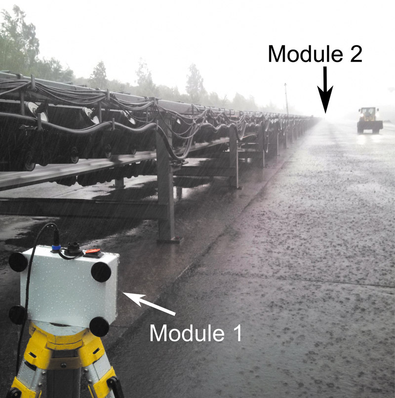
Fig. 2. Localisation measurement during heavy precipitation. // Bild 2. Lokalisierungstest bei starkem Regen. Photo/Foto: IMR
A similar application case arose for the localisation of a bunker discharge cart inside a coalbunker. The task was to localise the cart during its movement along rails. Usually a laser measurement system is operating here to track the cart. This system however was prone to failure under dusty conditions. In contrast, the UWB system was able to track and securely localise the cart even under such dusty conditions. Even the present multipath phenomena due to the small confined space in a concrete and steel environment had nearly no influence on the measurement.
As a step towards the automation of a reclaimer at a coal mixing place, the position of the reclaimer was tracked by the UWB system. Here a combination of two anchors 400 m apart plus a mobile tag was sufficient for the one dimensional position estimation. The mobile tag on the reclaimer continuously measured the distances to the anchors. Considering this one-dimensional case and implementing a plausibility test with the initial position of the reclaimer known, the second anchor can be seen as redundant since the machine can only move along a given track.
4 Sensor Fusion
Despite its many advantages the UWB system also has got certain disadvantages. Among others, these are the need for several fixed, stationary nodes, to be able to conduct a lateration. When employed underground, this means that a lot of anchors are needed since a line of sight to at least three anchors is needed for a three-dimensional position estimation using the lateration algorithm. Furthermore, the position of the anchors has an influence on the performance of the system when it comes to precision. Even for a very precise one-dimensional time of flight measurement, the precision of the whole system may drop, if the geometry of the anchors was chosen poorly.
To prepare the UWB system for underground use, these problems need to be tackled. The precision of a widespread underground localisation system based on UWB radio needs to meet the requirements even for disadvantageous geometries of the anchor positions. What is more, it is paradigm to reduce the number of anchors to a minimum, because the investment cost decreases with a decreasing number of anchors.
One solution is to make use of the so-called sensor fusion. With this method, the information of two or more sensors are fused in order to gain a better position information as would be possible with the individual information. This happens in a sensor fusion algorithm. This algorithm statistically analyses the information and then combines them. This way, flaws of the one sensor system can be compensated for by the other sensor systems (15).
Besides the UWB based localisation systems with sensor fusion there are also other approaches for underground positioning systems. As an example the UPNS 4D+ project can be mentioned. The scope of this project is the development of an underground deposit positioning, navigation and mapping system based on sensor fusion. Here a combination of inertial navigation and laser scanners is used.
Nonetheless, research at the IMR suggests that the UWB system is a good solution for the development of an underground localisation system. So it was decided, to develop an underground positioning system by means of sensor fusion of UWB and INS. The work is carried out in the following three projects.
4.1 Real-Time Mining Project
The idea for the development of a demonstrator for an underground positioning system for mobile underground equipment was first presented in the Real-Time Mining project. This project has received funding from the EU’s Horizon 2020 research and innovation programme under grant agreement No 641989. Additionally to the just mentioned sensor fusion of UWB and INS, INS is backed up by a laser scanner. Already here a sensor fusion is applied, to gain additional information about the velocity and the pose of the machine.
For the design of the system, two use cases were defined. Use case 1 is the precise positioning of mobile mining equipment such as a drill jumbo at the working face. Use case 2 is for the positioning of fast moving machines, e. g., shuttle cars, which requires a high update rate of the system. In both cases the UWB system is employed as an absolute system for the localisation in reference to the local coordinate system of the mine. Further, the information of the INS and the laser scanner will be used mostly in use case 2 to reach the required update rate. For the design of the system, an accuracy of at least 0.5 m within a 90 % confidence interval was defined.
A first test campaign was conducted at the “Reiche Zeche” mine of Freiberg Technical University (Figure 3). Especially the performance of the UWB system for both use cases was scrutinised there. The result is that for the two-dimensional dynamic use case already an accuracy of around 40 cm was achieved. For a stationary one-dimensional localization an accuracy of about 35 cm could be obtained while measuring across a 150 m long road heading.
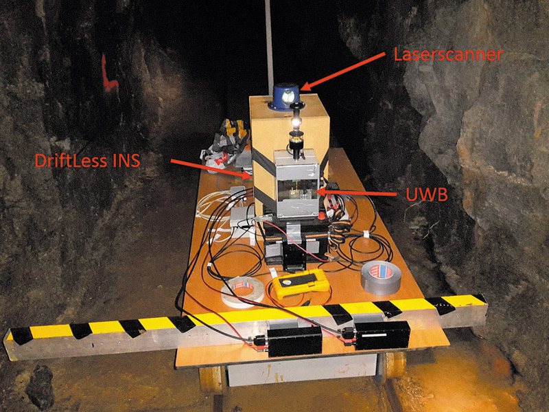
Fig. 3. Mine cart with sensors installed during the Real-Time Mining measurement campaign at the “Reiche Zeche” mine. // Bild 3. Hunt mit installierten Sensoren während der Real-Time Mining Testmessung im Bergwerk „Reiche Zeche“. Photo/Foto: IMR
Current work is focussed on algorithms for the filtering of the positioning data to gain an even more precise position information for the UWB system. Through this, it is expected to enhance the precision by a couple of centimetres. In the near future, work on the fusion algorithm will commence. Using this algorithm the information of the INS and the laser scanner can be included. Especially for the dynamic use case, an improvement in obtainable accuracy is expected.
4.2 SIMS
Further development of the demonstrator to be gathered from the Real-Time Mining project will be carried out in the SIMS project starting early 2017. The EU funds this project, too. The acronym SIMS stands for „Sustainable Intelligent Mining Systems“. The aim of the project is to conduct an underground position estimation using more than ten UWB anchors. Here as well the sensor fusion will be utilised. Unlike in the Real-Time Mining project this time a low-cost and less precise INS will be used. The reason is to test if a common INS, as it is used in, e. g., smartphones is sufficiently precise at lower investment costs.
Next to the positioning case, it is intended to use the UWB anchors as an emergency mesh-network for communication. This application case can be very useful if a widespread use of UWB anchors in a mine is present. With an independent, redundant communication system based on UWB, communication can preserved in the event of a mine disaster. Namely a battery driven system does not rely on cables which could be destroyed in the emergency case. What is more, the potential loss of single cells in the mesh-network can be compensated for with the other anchors. The widespread trial will be conducted over the next three years in a Swedish underground mine.
4.3 EMD Project
Another development towards the solution for an underground positioning system is the EMD project, which receives funding of the German government in the scope of the ZIM-initiative. The aim is to develop a shotcreting machine together with the company GTA that can shotcrete a tunnel in an automated way and guided by sensors. Not only the shotcreting process as such will be surveilled but also a subsequent automated documentation is intended once the works finished.
In order to achieve this, different sensors for the measurement of the tunnel profile will be mounted at the end of the boom. These sensors need to be positioned. For this reason a positioning system on the basis of UWB is used. To improve especially dynamic scenarios of the boom, a sensor fusion between UWB and an employed INS will be carried out.
The necessary accuracy for this project is in the centimetre range. Next to algorithms for an improved position estimation, also the geometry of the UWB anchors needs to be chosen carefully. As described before this can influence the accuracy decisively. A detailed technical plan is drawn up just before completing this article. First results are expected for the end of 2017.
5 Conclusion
In this article an underground positioning system based on the UWB technology, capable for the automation within the Mining 4.0 initiative, is presented. Technical as well as physical properties of the system are briefly explained. Additionally a short overview of past, mining relevant application cases is given.
In the end an approach for the optimization of the system by means of sensor fusion is described. In this context first results of the Real-Time Mining project are exposed. Afterwards, two other projects concerned with the development of an underground positioning system based on the sensor fusion of UWB and INS are unveiled. Especially their respective focus of attention of development at the IMR is explained. The results of these two initiatives will be presented in more detail in the future.
References / Quellenverzeichnis
References / Quellenverzeichnis
(1) Gu, Y.; Lo, A.; Niemegeers, I.: A survey of indoor positioning systems for wireless personal networks. IEEE Commun. Surv. 11, 2009,
pp 13 – 32.
(2) Research and Markets: Indoor Location Market by Positioning Systems, Maps and Navigation, Location based analytics, Location based services, Monitoring and emergency services – Worldwide Market Forecasts and Analysis (2014 – 2019). 2014. Accessed October 2016. http://www.researchandmarkets.com/research/cmx9n8/indoor_-location
(3) Huang, H.; Gartner, G.: A Survey of Mobile Indoor Navigation Systems. In: Chapter 20 Cartography in Central and Eastern Europe. Springer Verlag, Heidelberg/Germany, 2009, pp. 305 – 319.
(4) Win, M. Z.; Dardari, D.; Molisch, A. F.; Wiesbeck, W.; Zhang, J.: History and Applications of UWB. Proc. IEEE, vol. 97, no. 2, 2009, pp. 198 – 204.
5) Mahfouz, M. R.; Zhang, C.; Merkl, B. C.; Kuhn, M. J.; Fathy, A. E.: Investigation of High-Accuracy Indoor 3-D Positioning Using UWB Technology. IEEE Trans. Microwave Theory Techn, vol. 56, no. 6, 2008, pp. 1316 – 1330.
(6) Federal Communications Commission: First Report and Order: Revision of Part 15 of the Commission’s Rules Regarding Ultra-Wideband Transmission Systems. Washington, D.C., 2002.
(7) Bundesnetzagentur: UWB, das Kurzstrecken-Kommunikations- und Sensor-Funksystem, 2015.
(8) Kuhn, M.; Mahfouz, M.; Turnmire, J.; Wang, Y.; Fathy, A.: A multi-tag access scheme for indoor UWB localization systems used in medical environments. In: Proceedings of the 2011 IEEE Topical Conference on Biomedical Wireless Technologies, Networks and Sensing Systems (BioWireleSS), Phoenix/USA, 16th to 19th January 2011, pp. 75 – 78.
(9) Data Sheet PulsOn 410. Time Domain, Huntsville/USA, 2013. 320-0289E.
(10) Hammer, F.; Yudanto, R.; Neumann, K.; Pichler, M.; Cockx, J.; Niestroj, C.; Petré, F.: Performance Evaluation of 3D-Position Estimation Systems. IEEE Sensors Journal vol. 16, Issue: 16, Aug.15, 2016, pp. 6416 – 6424.
(11) Chehri, A.; Fortier, P.; Tardif, P. M.: Geolocation for UWB Networks in underground mines. In: Wireless and Microwave Technology Conference. WAMICON ‚06. IEEE Annual, 2006, pp. 1 – 4.
(12) Emami, S.: UWB communication systems: Conventional and 60 GHz : principles, design and standards. New York, NY: Springer, 2013.
(13) Daixian, Z.; Kechu, Y.: EKF Localization Based on TDOA/RSS in Underground Mines Using UWB Ranging. Signal Processing, Communications and Computing (ICSPCC), IEEE International Conference, 2011.
(14) Neumann, K.; Eichentopf, B.; Niestroj, C.: Ultra-Wideband Radio Technology for the Heavy Industry. World of Mining, Surface & Underground 67 (2015) No. 5: pp. 307 – 313-
(15) Elmenreich, W.: Sensor Fusion in Time-Triggered Systems. Dissertation. Wien, 2002, pp. 7 – 9.