The cooperation between the TML Technik GmbH, Monheim/Germany, and the Institute for Advanced Mining Technologies (AMT)of the RWTH Aachen University, Aachen/Germany, will create a synergy between the innovative construction and design of telescopic arms and the development of intelligent, mining-capable condition monitoring systems. As a result, an intelligent telescopic arm not yet available on the market will be build. A mining-capable system for online load monitoring and condition monitoring of individual machine components has never been used before in any comparable machine. For an optimized design of the new telescopic boom, innovative technical approaches will be applied and evaluated accordingly. The investigation and definition of parameters of the dissolution process will enable optimal and efficient operation in the future. The realization of open communication interfaces, and the definition of standards for data communication in the field of telescopic booms, result in a platform for future emerging industry 4.0 services under the special requirements of mining. Thus, a step towards attaining the goal of what is internationally commonly described as “the autonomous mine of the future” is taken. Within this publication, the associated project as well as the stress tests carried out in the first phase of the project in a mine in Russia will be presented. Based on these elaborations, an overview of the evaluation, as well as possible future analyses will be provided.
1 Introduction to the project
The research project “The intelligent telescopic boom for extreme conditions of use” is funded by the Federal Ministry for Economic Affairs and Energy as part of the “Central Innovation Program for SMEs”. The aim of the project is the development of a robust, self-monitoring telescopic boom, which is suitable for adverse environmental conditions in the raw materials industry. Central aspects of the project are the conceptual design of the telescopic boom by the company TML Technik GmbH, Monheim/Germany, as well as the equipment of the boom with a multi-monitoring system by the Institute for Advanced Mining Technologies (AMT) of the RWTH Aachen University, Aachen/Germany. The sensor-based monitoring of the scaling process aims at increasing the efficiency and the lifespan of the machine. The multi-monitoring system should reliably warn against operating situations of high load and, if necessary, reduce machine performance. Simultaneously, this concept creates the basis for tele- or office-remote-controlled operation (Mining 4.0). The telescopic boom is designed as an innovation for application in extreme environmental conditions (dust, dirt, rockfall, vibration, impact, moisture), especially in gypsum and anhydrite mining.
The new design of the telescopic boom is due to changed legal regulatory conditions and intended to increase efficiency, durability and occupational safety. A new safety regulation in Russian mining prohibits manual work above a height of 3,5 m. This will result in the need to resort increasingly to the use of machines. The telescopic boom can be used to excavate at a height of up to 13 m without having to move the vehicle. The propulsion of the tool relies solely on the telescopic operation of the boom.
Furthermore, the whole drift face can be scaled without moving the machine, since the telescopic boom can be rotated 360°. Fully integrated supply lines further add to the ruggedness of the telescopic boom. By constructively overcoming the safety-critical range of the telescopic arm, working in close vicinity to the scaling process should be made safer for man and machine. At the same time, a reduction of manoeuvring can be achieved, which will lead both to an increase in efficiency during operation and a reduction of operation costs.
In order to be able to precisely determine the stress acting on the telescopic boom, various mechanical parameters, and parameters within a reference measurement had to be determined. The stress within the structure of the telescopic boom was determined with the help of strain gauges. Additionally attached sensors, such as structure-borne sound sensors, allow for a more detailed representation of the loads.
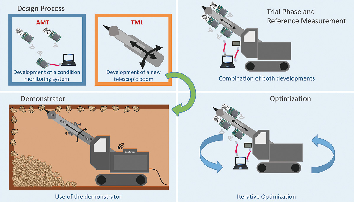
Fig. 1. Overview of the research project. // Bild 1. Arbeitspakete des Forschungsprojekts.
Figure 1 illustrates the individual phases of the project. The measured variables determined in the reference measurements serve as a basis for further work packages. In addition to optimising the design of the boom, the development of a suitable measuring system will be the focus of the research in the future. Finally, the combination of the new boom and sensor system will be evaluated in further demonstrative experiments.
2 Reference measurement
In preparation for the development of the multi-monitoring system, the real operating conditions of a telescopic boom were recorded during a two-week operation measurement in a gypsum/anhydrite mine in Novomoskovsk/Russia.
2.1 Measuring concept
In the run-up to the measurement campaign, a boom was equipped with conventional measuring technology to record the loads during various reference scenarios. For this purpose, a measuring system was set up which was conceived only for the duration of the reference measurement. In order to obtain the most complete picture of the scaling process, transducers have been installed to detect the wide range of mechanical parameters. The schematic structure, including all sensor positions of this measuring system, is depicted in figure 2.
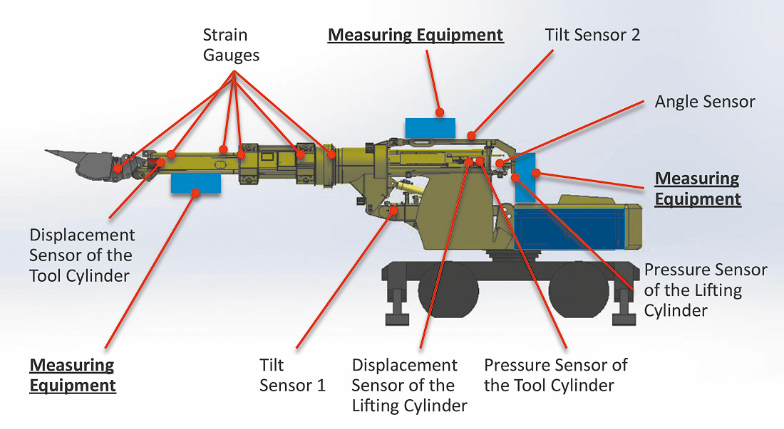
Fig. 2. Schematic illustration of the telescopic boom including the sensor positions of the measuring system. // Bild 2. Schematische Abbildung des Teleskopauslegers inklusive der Sensorpositionen des Messsystems.
The primary focus of the measurement campaign was to determine the real mechanical stresses which acted on the boom during the scaling process. A total of 17 strain gauges were realised for the acquisition of the most relevant stresses. To determine the kinematic parameters during the scaling process, the travel path of the telescopic boom, as well as the angular position of the tool were recorded via displacement sensors. Tilt sensors recorded the inclination of the arm. Several pressure sensors recorded the hydraulic pressures of the working cylinders. A triaxial structure-borne noise sensor recorded vibrations in three spatial directions directly on the scaling arm. All sensors were connected via data cable with conventional measuring technology. The hardware for recording the sensor signals was installed in three switch cabinets. Via a wired data connection between the switch cabinets, the sensor data was forwarded to a measuring computer, which was also installed in one of the switch cabinets.
2.2 Preparation of the measuring
The measuring system was first pre-assembled and tested at the AMT. Subsequently, the fully wired measuring system was shipped to Russia. In the workshop of the mine, the control cabinets were placed in the designated positions and the sensors were installed on the telescopic boom. This procedure minimised unexpected problems during commissioning of the measuring system on site. The implementation of the measuring system is given in figure 3, which shows the installation of one of the control cabinets on the telescopic boom.
Due to the harsh operating conditions during the operational measurement, it was to be expected that part of the conventional measuring technology would fail. Therefore, deliberately redundant strain gauges were installed. To minimise the risk of failure, the measuring points were protected against the dissolving rock by means of protective devices. The measuring system was designed for a trial period of approximately two weeks. An impression of the DMS measuring points is given in figure 4.
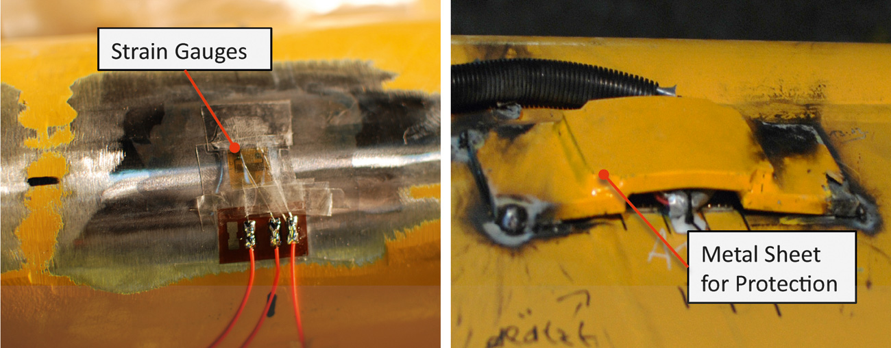
Fig. 4. Unprotected strain gauge measuring point (left); protected DMS measuring point (right). // Bild 4. Ungeschützte DMS-Messstelle (links); geschützte DMS-Messstelle (rechts).
2.3 Conducting of the measurement
The aim of the measuring campaign was the determination of real stresses on the telescopic boom during operation. To be able to record every possible operating situation, the measuring system operated continuously. The data recording was started before the beginning of each respective shift. Towards the end of the shift, data recording was stopped and the data was saved on an external hard disk. Thus, in addition to the actual work cycles of the machine, other types of strain were recorded, such as the stresses during driving periods to the place of use. In order to be able to assign the recorded data to the respective work cycles during the later data evaluation, a protocol was kept during the entire measurement campaign on the progress of the scaling process.
It was recorded at each time which tool was worked with, whether the side walls or the drift face were worked on, whether the vehicle was moved to a new location or whether the vehicle was switched off for maintenance. Additionally, all work was continuously documented on video. In total, measurements of regular operations were carried out on five days. A typical scaling process is illustrated in figure 5. Here, the side wall is scaled with a hydraulic hammer.

Fig. 5. Working at the sidewall. // Bild 5. Beraubevorgang am seitlichen Stoß.
2.4 Preliminary results of the measurement campaign
By analysing the results from the measurement campaign, the real stresses on scaling tools can for the first time be determined and correlated with the respective work cycles. This way, highly stressful working methods can be identified and analysed in more detail. As an example, the course of a single mechanical stress signal is discussed below.
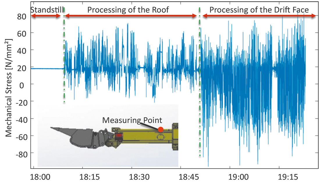
Fig. 6. Recorded mechanical stresses in different working modes. // Bild 6. Gemessene Bauteilspannung in unterschiedlichen Arbeitsmodi.
Figure 6 shows the measured course of the mechanical stress signal over a period of an hour as well as the point in time at which the signal was recorded on the telescopic arm.
At the beginning of the series (around 6 PM), the telescopic boom stood still, without having to do any work. A constant mechanical stress is measured, which corresponds to the strain caused by the weight of the tool. At 6.10 PM the scaling process began. First, the roof was worked on. Around 6.50 PM work started on the drift face. During the processing of the drift face, much greater amplitudes can be observed which can be explained by a comparative examination of the working methods at the drift face and the roof. During the work of the roof, the telescopic boom is mainly affected by tensile and compressive forces, whilst during work on the drift face, a bending moment additionally acts on the structure. This bending moment is caused by the angled position of the tool in relation to the boom. Figure 7 illustrates the two different working modes.
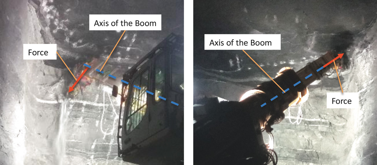
Fig. 7. Direction of force during scaling: drift face (left), roof (right). // Bild 7. Kraftangriffsrichtungen beim Berauben: Stoß (links); Firste (rechts).
Based on the recorded data, an estimation of the forces during the scaling process will be made in the further course of the project. Based on these forces, realistic FEM-simulations and multi-body simulations can be performed. These simulations can serve as a basis for design improvements. An approach to determining the process forces at work is shown in figure 8.
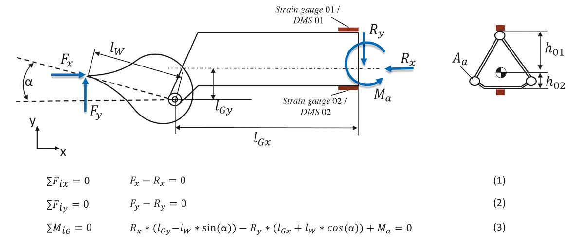
Fig. 8. Theoretical approach to determine the process forces (top left: sketch of the telescopic boom including the tool, top right: cross-sectional profile of the telescopic boom; bottom: equations for balance of forces). // Bild 8. Theoretischer Ansatz zur Bestimmung der Prozesskräfte (oben links: Skizze des Teleskopauslegers inklusive des Werkzeugs; oben rechts: Querschnittsprofil des Teleskopauslegers; unten: Gleichungen zum Kräftegleichgewicht).
By means of an equilibrium of forces between Fx and Fy acting on the tool and the reaction forces and moments (Rx, Ry, Ma)in a sectional plane of the telescopic boom, three determination equations can be derived for calculating the process. The measured angle α is included in the calculation. It describes the position of the tool in relation to the axis of the telescopic arm. The cutting plane in which the reaction forces are applied is chosen to coincide with the plane in which mechanical stresses are measured on the telescopic boom. Using mechanical stress in two points in the section place, two more equations of determination can be derived (Figure 9). The equations given for the stress calculation are based on a superposition of bending stresses, longitudinal stresses and shear stresses.
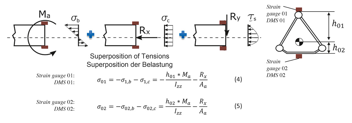
Fig. 9. Integration of strain measurement signals (above: superposition of the stresses from bending stress, longitudinal stress and shear stress; below: equations for the description of the component stresses). // Bild 9. Einbindung der Dehnungsmesssignale (oben: Superposition der Belastungen aus Biegespannung, Längsspannung und Schubspannung; unten: Gleichungen zur Beschreibung der Bauteilspannungen).
Equations 1 to 5 form a linear system of equations whose solution provides the process forces sought. In this analysis, only the static part of the process force was considered. Dynamic effects are not taken into account. For this reason, the measured stress signals must be reduced by a low-pass filter to their (quasi) static component. The result of the calculation provides an estimation of the contact pressure of the tool on the drift face and the roof. The evaluation of the results is still pending. Future models should take the dynamic effects during work cycles into consideration.
The data also provides valuable information for the design of the monitoring system that is to be developed. The system, e. g., can be designed based on the real mechanical stresses. Furthermore, places of high strain can be identified, on which the monitoring system will be installed.
3 Conclusion and outlook
Within the framework of the presented research project, an intelligent telescopic boom will be developed for underground scaling. To provide a basis for the design improvements of the boom and the development of the monitoring system, a telescopic boom was equipped with conventional measuring technology and the scaling process was measured. Based on the measured data, the individual processing cycles of the scaling process can be analysed in detail. Initial evaluations have shown that there are significant differences in the stresses occurring during scaling drift faces and roofs.
In the future, detailed data analyses will reveal potential for improvement, which will be incorporated into constructive measures. Furthermore, a monitoring system will be developed based on the findings from the measurement campaign. The conclusion of the research project will be a demonstrator phase in which the monitoring system and the optimised design will be tested.
Acknowledgments
We wish to thank Dr.-Ing. Ralph Baltes and Felix Leaman, M.Sc. for their collaboration on this publication. Furthermore we would like to thank the company TML Technik GmbH for the good cooperation.
This research project is funded by the AiF as part of the Central Innovation Program for SMEs (ZIM) by the Federal Ministry for Economic Affairs and Energy under grant number ZF4010402LL6 on the basis of a resolution of the German Bundestag.