1 Introduction
According to the World Coal Association (WCA), coal provides more than 41.1 % of the world’s primary energy demands and therefore is one of the most important resources for energy. With 8,022.5 Mt in 2014, the world coal production has reached a new record of production. However, the commodity price for coal has been decreasing from approximately 70 €/t to 40 €/t within the last five years. Therefore, the pressure of competition has been increasing sharply and the production needs to become more efficient within the existing mines. It is necessary to decrease the total amount of material leaving the mine to increase the productivity of coal mines. This can be achieved by keeping as much waste rock untouched as possible and thus, increasing the valuable-to-waste ratio. Nevertheless, despite centuries of efforts on realising an autonomous method for distinguishing the highly abrasive waste rock from the valuable coal there is no current solution viable for production yet, although some of the latest technologies have been particularly promising (1, 2, 3, 4, 5, 6).
2 Laser-induced breakdown spectroscopy
Laser-induced breakdown spectroscopy (LIBS) is an atomic emission method utilising a laser-generated plasma as an excitation source. It can be applied to determine the elemental composition of substances in a solid, liquid or gaseous state both quantitatively or qualitatively. Handling a LIBS measurement is relatively easy and the sample to be tested does not need special preparations. One major advantage compared to methods such as x-ray fluorescence (XRF) is the ability to detect light elements such as carbon, silicon and sulphur. Plasma generation is limited to a few milliseconds and therefore, there is a high possibility to gain a high amount of information within a short range of time. Additionally, a high number of measurements decreases the possibi-lity of inaccuracies in the generated spectra (7, 8, 9).
LIBS has been developed since the early 1960s and many applications have been found how to utilise it since then. However, the majority of applications is limited to laboratory environments. Within the last decade, efforts have been made to include LIBS into industrial applications, such as the material analysis of metallurgical slags during production, the determination of the elemental composition of borehole cuttings and the analysis of aluminium scrap (10, 11, 12).
A low-energy laser pulse is focused onto one spot of the sample during a LIBS analysis. The focus is set onto the surface in case it is a solid; in case it is a gas, the focus is set into a defined spot in the gas chamber. To analyse liquids the focus can also be set into the liquid which needs to be transparent in order to achieve results. Otherwise, the focus needs to be set on the surface as well. The power density of the laser pulse can amount to several Gigawatts per cm2 due to the pulsed energy supply. The sample material in the focus of the laser beam heats up to 10,000 to 25,000 K and a few microns of the material vaporise. An ionisation of the included electrons initiates the plasma generation within the vapour. The electrons are excited into higher energy states. The moment the plasma temperature decreases again the electrons and ions try to return into their ground states and recombine to mole-cules or neutrons. Energy is released in form of photons which are characteristic for the atoms included in the sample. The light of the photons can be collected and evaluated. Figure 1 shows the setup of a typical LIBS apparatus. It includes the laser, a spectrometer for collecting the photons emitted by the plasma, a detector, e.g. Charged-Coupled Device (CCD), to transform the light to electrical signals and a computer to generate a spectrum (7, 9, 13, 14).
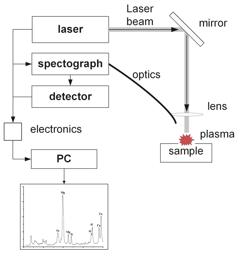
Fig. 1. LIBS setup (8). // Bild 1. Aufbau einer LIBS-Apparatur (8).
3 Automation of underground coal mines
3.1 Elements for mine automation
The main aims of automating mining processes are increased productivity and efficiency, increased machine performance with lower downtimes as well as decreased utilisation of personnel in hazardous areas. In order to gain sufficient information for automated longwall operations, four key elements need to be implemented (Figure 2). However, different levels of sophistication are required depending on the targeted automation level (3, 4, 5).
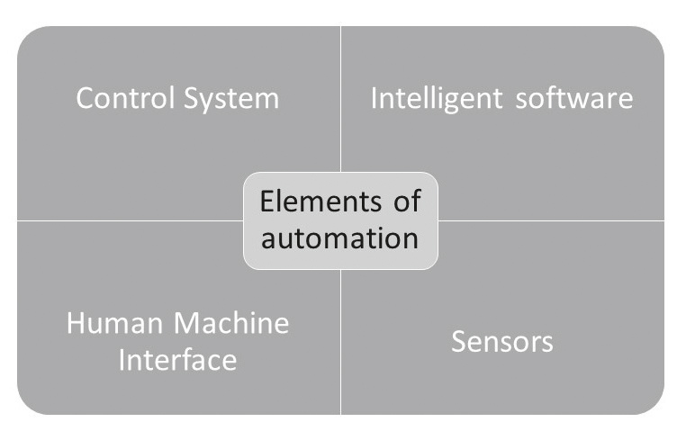
Fig. 2. Elements required for mine automation. // Bild 2. Elemente zur Umsetzung der Bergwerksautomatisierung.
The control system is required to realise the communication between the existing machine components in the defined system, whereas the intelligent software enables the operation of the machine components. The human machine interface determines the level of possibilities to influence the overall process. Furthermore, it enables the personnel to overview the automation process. Several sensors are needed to meet different requirements. First, sensors for determining the positon and alignment of all components need to be implemented. Second, sensors for determining material characteristics are required for distinguishing the different groups of material which are to be separated. This paper focusses on the second group of sensors (3, 4, 5).
3.2 Boundary layer detection and horizon control – experiences at the IMR
The Institute for Mineral Resources Machine Technology (IMR) at the RWTH Aachen University in Aachen/Germany has been working on material analysis for horizon control and boundary layer detection for more than a decade. The most promising results were achieved in utilising thermal imaging to detect boundary layers within the coal seam. Thermal imaging is an imaging method based on the temperature differences of monitored objects. This technology has been available on the market since 2010. However, it also has some drawbacks. First, the position of the camera is limited to areas on the shearer where the view onto the seam is as clear as possible. Depending on the place of choice the camera can be impaired by falling rocks and dust. Second, the technology is dependent on existent boundary layers within the seam, since it is not always possible to detect the horizon of the seam. Depending on the rock strata, a part of the top coal needs to remain in the seam, so that the transition between roof and coal seam is not visible for the camera. Hence, it is not visible how much top coal is kept uncut. Third, the technology is only feasible for qualitative distinction of coal and waste rock. It is possible that existent boundary layers might not be visible in case the material composition slightly changes within the seam (3).
A technology which was tested in a totally different environment, but which shows high potential for distinction of coal and waste rock is LIBS. The technology was first introduced in 2008. Back then, it was utilised for online-modelling of limestone depo-sits during drilling of blast holes in open pit mines. It could be proven that it is possible to utilise LIBS in mining operations despite the harsh conditions affected by dust, vibration, shock and mist. A ruggedized device, which enabled the installation of LIBS on a drill rig, was designed to enable measurements during the drilling process (Figure 3). This way, it was shown that time-demanding measurements in the laboratory can be substituted (10).
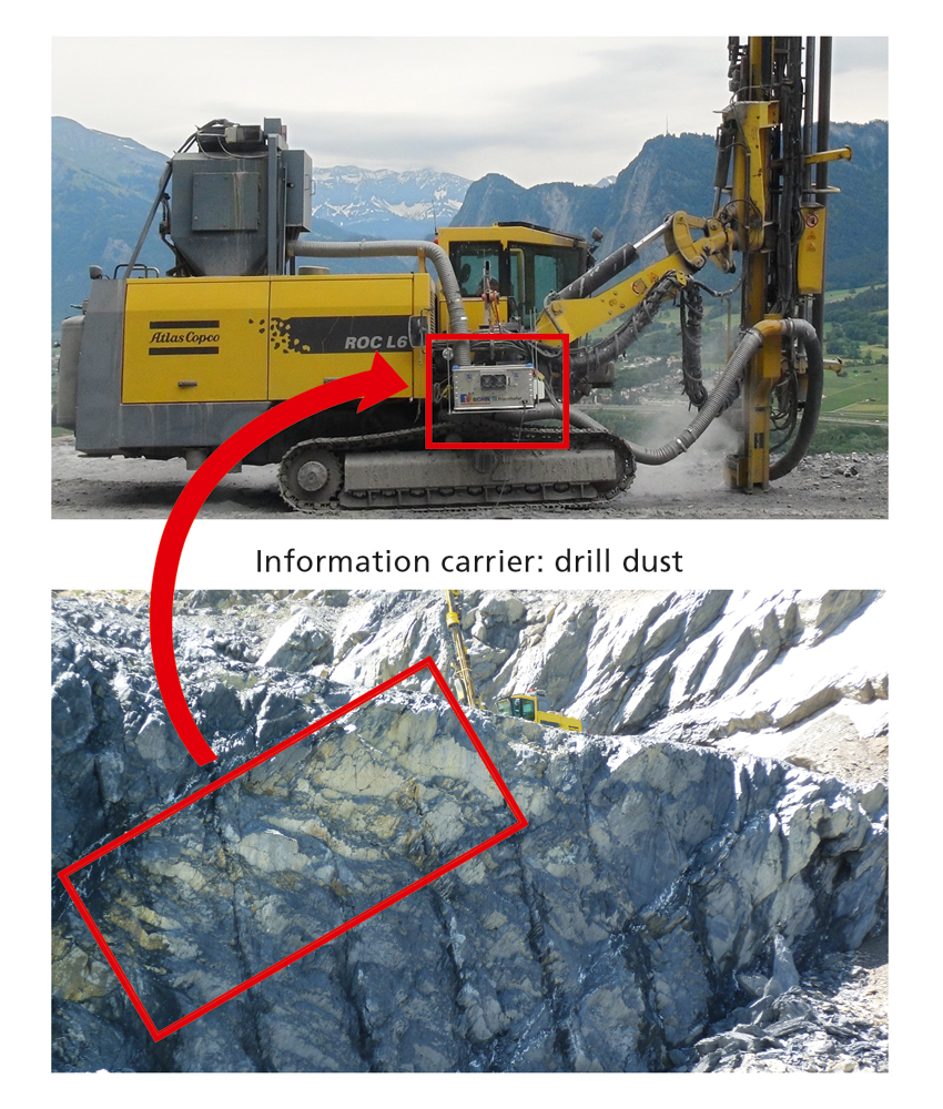
Fig. 3. LIBS on a drill rig for updating deposit models. // Bild 3. LIBS-Apparatur an einem Bohrgerät zur Aktualisierung von Lagerstättenmodellen. Photos/Fotos: Fietz
The promising results from the first LIBS project as well as the drawbacks from thermal imaging led to the conclusion that LIBS might also be feasible for the distinction of coal and waste rock in underground coal mines. However, the conditions in coal mines are very different to other underground mines. This article presents the special challenges in underground coal mines and gives an overview on current results of the project.
4 LIBS for material characterisation in underground coal mines
4.1 Operational challenges for LIBS
During the coalification process methane (CH4) was created which is one of the major hazards in underground coal mines. CH4 occurs between the coal layers and can be released due to tension releases of the extracted material during the cutting pro-cess. As soon as it is released, a volumetric concentration of 4 to 14 %/m3 is suffice to become potentially explosive. As can be seen in Figure 4, three components are needed to initiate an explosion: oxygen, combustible and ignition source. Only 0.28 mJ of released energy and a minimum of oxygen are needed to induce a methane explosion. Consequently, the explosion can initiate a chain reaction with the surrounding area by volume dilatation of the air. The pressure from the methane explosion can build up to 7.2 bar which is sufficient to induce another explosion: a (coal) dust explosion. Both types of explosion together can build up a pressure of 11 bar (10, 15, 16, 17, 18).
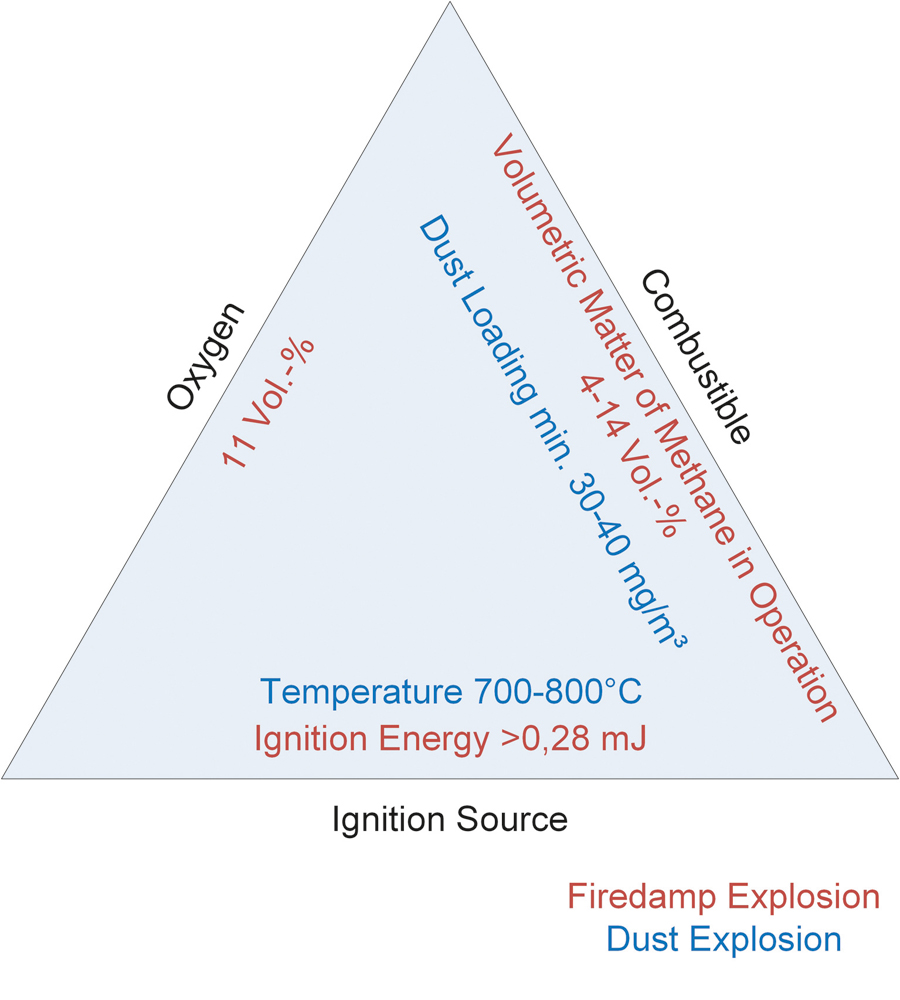
Fig. 4. Factors affecting an explosive atmosphere (16). // Bild 4. Einflussfaktoren in einer explosionsfähigen Atmosphäre (16).
Additional to the special conditions due to the firedamp atmosphere, the environment in underground coal mines is challenging for the operation of the equipment as well. Increased temperatures and a humidity up to saturation as well as increased vibration and shock can affect the availability of all components to be used. “Since underground hard coal mines usually have to face continuous hazards of firedamp atmosphere, all developments have to be with regard to explosion-proof design. In the European Union, this is regulated by the so-called ATEX Directives which require a mandatory certification of all devices to be used in explosive atmospheres. They include numerous normative guidelines for the design of electric and non-electric devices” (19).
The energy of the laser beam itself usually varies between 10 and 500 mJ. Depending on the application, such as analysing liquid solutions, it is best to increase the pulse energy to a minimum of 200 mJ or higher. Water is a good absorber of energy and therefore decreases the energy generating a plasma in the focus of the laser beam. The temperature of plasma in water is much lower than on solids and hence, the signal loss of LIBS spectra can be significant. In contrast to the higher requirements on the laser itself, the given energy limitation of < 0.28 mJ clearly sets a limit to the operation of a laser in explosive atmospheres. An operation of LIBS directly at the mine face is not possible (10, 14, 20).
4.2 Considerations for enabling LIBS in explosive atmospheres
In order to realise LIBS for material analysis in explosive atmospheres, several considerations need to be taken into account. First, the explosive atmosphere due to methane requires the design of an explosion-proof enclosure which allows for LIBS mea-surements inside of it. Consequently, the material to be analysed needs to be transported into this enclosure so that an ignition of the laser beam does not result in a potential explosion. Taking into consideration that the material to be analysed needs to be transported into an enclosure, it is most sensible to use material of fine grain size, such as the generated dust which should be representative for the extracted material. The dust which is generated due to the extraction process gets dispersed by water directly at the source of formation, i. e. at the seam. Figure 5 depicts a sketch of the system boundaries between explosive and explosion-proof atmosphere.
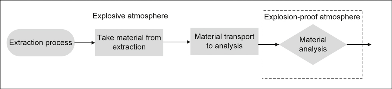
Fig. 5. Principle of LIBS for underground mining operations in explosive atmospheres. // Bild 5. Schematische Darstellung des Verfahrens zur LIBS-Analyse und Einteilung der Zonen.
4.3 Development of enclosure for LIBS analysis
Figure 6 shows the general design of the developed device for explosion-proof analyses. The design of this enclosure included the considerations of available guidelines. However, it is only based on the given guidelines because currently there is none which allows for an enclosed system to re-open during operation. All available systems require the complete closure during the lifetime of operation.
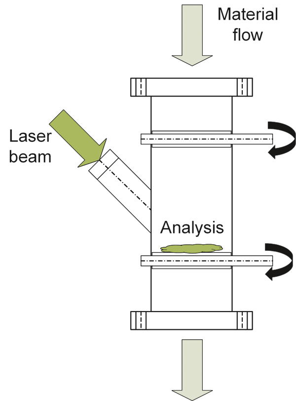
Fig. 6. Design of explosion-proof enclosure for analysis in explosive atmospheres. // Bild 6. Konzept der explosionsgeschützten Kapselung für Analysen in explosionsfähiger Atmosphäre.
The material to be analysed is fed from the top of the chamber and falls onto the lower shutter by gravitation. The lower shutter also is used as area of analysis on which the laser is focused during analysis. The laser beam is focused through an adapter which is covered with a quartz lens. According to the project results on the drill rig, the thickness of the lens is limited to a maximum of 10 mm. In the case of this device the thickness can be chosen even thicker, depending on the stress in a possible explosion. The reason for the difference in thickness is the focal length (21). There is more distance between the focus and the lens due to the adapter. Feasibility tests with a LIBS system showed that the angle of the adapter for the laser (beam) can be used for operation.
At this point, it needs to be mentioned that the whole process which is going to be described in this article is still on a methodological level, thus, there is currently no device which can be used underground.
4.4 LIBS analysis on coal and waste rock
4.4.1 Distinction of coal and waste rock
In order to figure out if LIBS is feasible for the distinction of coal from waste rock, both materials were extracted separately from various coal mines and analysed. Figure 7 shows a LIBS spectrum of coal and waste rock. The x-axis shows the wavelengths of the emitted photons whereas the y-axis represents the intensities of each emitted wavelength. In this case the spectrum is limited to the wavelengths 240 to 380 nm, but depending on the selected spectrometer a wider range of the spectrum can be used as well (10).
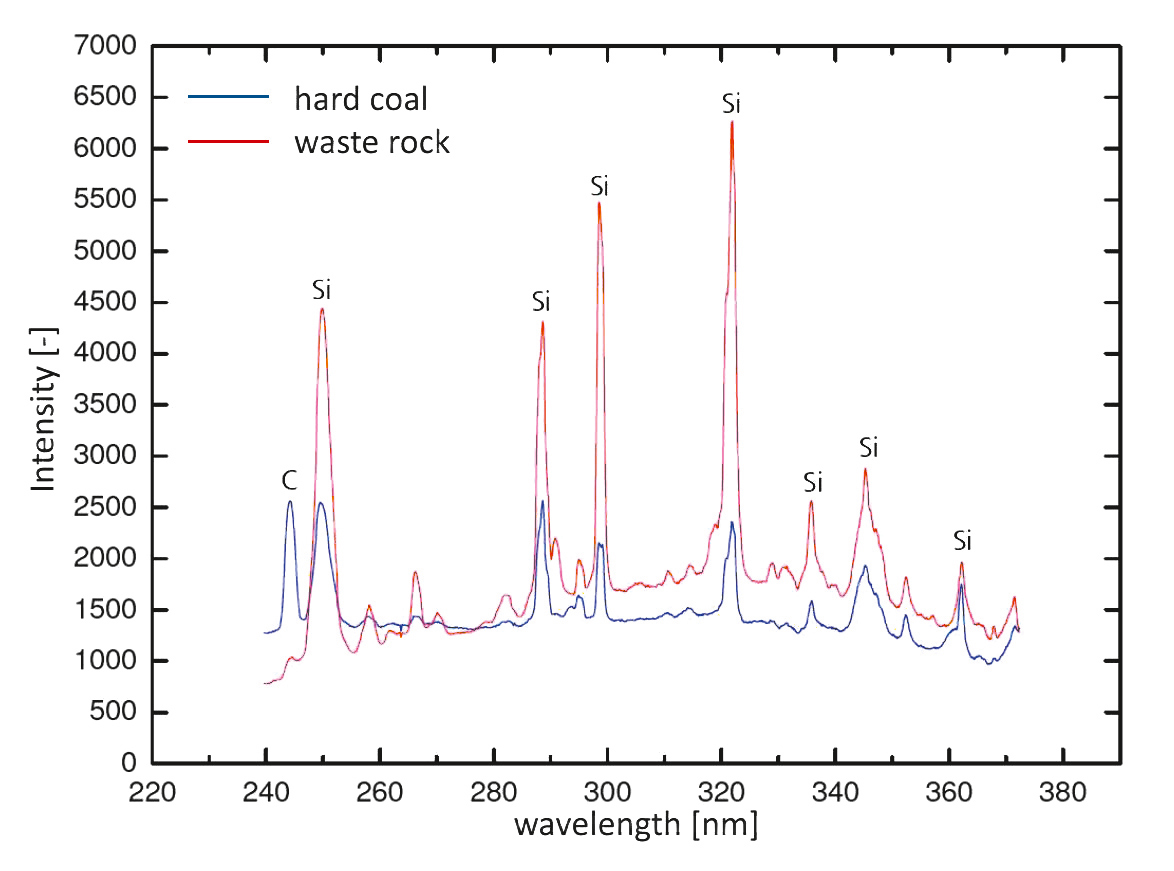
Fig. 7. LIBS spectra of coal and waste rock (10). // Bild 7. LIBS-Spektren von Kohle und Nebengestein (10).
The spectrum shows that a qualitative distinction is almost not possible because both materials include the same elements, resulting in very similar LIBS spectra. On the contrary, it also shows that according to their characteristic peaks coal and waste rock consist of different amounts of silica and carbon. It is known from reference tests with RFA that other elements such as iron, aluminium, manganese and titan can also be used for distinction of coal and waste rock. Therefore, a quantitative distinction between coal and waste rock with LIBS is possible (10, 15).
4.4.2 Analysis on wet dust samples
As already mentioned, the material to be analysed consists of dust which was liberated during the extraction process and water which is utilised to suppress the liberated dust. However, there is currently no knowledge about the total amount of liberated dust. Based on a broadly executed benchmarking of dust generation in U.S. American coal mines, Rider and Colinet determined that approximately 40 % of all dust particles smaller than 35 µm originate from cutting (22). These numbers are based on measuring the airborne dust, but not the total dust generation. Rider and Colinet also estimated the overall dust which is generated during the overall mining process amounts to 10 % of the total mass production. This number is to be considered carefully because it is a pure estimation and a direct comparison to the given 10 % of total mass production is not possible.
Therefore, determining the exact amount of dust available for analysis is not as easy as might have been expected. This aggravates the determination of the exact water-to-dust ratio and hence, the determination of the ideal parameters for LIBS analysis. Because of this, a test series with varying water-to-dust ratios was conducted with LIBS. It was known from Gaastra that LIBS measurements with wet coal and waste rock samples were limi-ted to a minimum of 5 % solid. Additionally, at 5 % there was only one characteristic line which could be used for distinguishing coal and waste rock from each other (10). So the new aim was to determine if a lower dust concentration could result in evaluable results as well. The expectation of achieving better results was reasonable taking into account that LIBS technology has evolved within the last six years. In order to find out the new detection limit of LIBS in water-dust mixtures, samples of pure coal and waste rock were mixed with different amounts of water, respectively. The lowest amount of dust which was added to the water was 1 %, the highest amount of dust was 50 %.
The LIBS apparatus used for the tests was a customised LTB (Lasertechnik Berlin) OEM, utilising a serial 1064 nm Nd:YAG laser with a maximum of 150 mJ energy and a pulse rate of 10 Hz. The amount of pulses for one analysis can be adjusted up to more than 300 pulses by using a chopper. The spectrometer is an Aryelle 400 spectrograph, the detection of the spectral lines is conducted with a CCD. One of the special properties of the customised OEM is the possibility to analyse high spectral ranges while using a high spectral resolution as well. This property enables the determination of spectral lines which are located very close to each other.
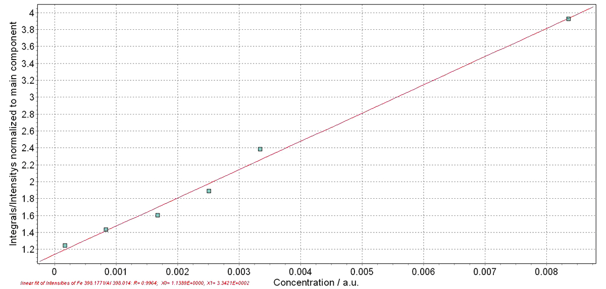
Fig. 8. Calibration curve of waste rock at different water-to-dust ratios at Fe398.1771 nm and Al 398.014 nm lines. // Bild 8. Kalibierkurve von Nebengestein bei unterschiedlichen Wasser-zu-Staub-Verhältnissen für die Fe-Linie bei 398,1771 nm und die Al-Linie bei 398,014 nm.
A typical LIBS spectrum looks like the one depicted in Figure 7. However, looking at only one spectrum does not give the possibility of quantifying the elements contained in the sample. In order to achieve a quantitative result it is necessary to gain several spectra of different samples and compare them to each other. Nevertheless, it is also not possible to just compare two individual lines because the intensity of an individual line does not give any information of the quantity of the observed element. For quantification, it is necessary to compare the ratio between two different elements contained in both samples. The software provided by LTB Lasertechnik Berlin compares one trace element to one main element through dividing the main element by the trace element. Figure 8 shows the calibration curve for iron (Fe) at 398.1771 nm at different water-to-dust ratios. The respective intensity ratios are normalised by the aluminium (Al) lines at 398.014 nm. The x-axis represents the percentage of Fe within the dust-water suspension whereas the y-axis represents the relative intensity ratio between Fe and Al.
The lowest percentage of dust which could be measured in water was 1 M.- % of waste rock. Hence, a reduction of 80 % material present in the liquid could be achieved compared to the first attempts of analysing dust in water. This is a huge success and brings LIBS for material analysis in underground operations a step closer to reality.
5 Conclusion and outlook
The automation of underground coal mining operations has been gaining significant importance due to the cost pressure on the market. Several considerations in order to fulfil automation as well as to meet the coming expectations on the market need to be taken into account. One area of interest to push automation is to find solutions for distinguishing coal from waste rock during extraction. The IMR has conducted several projects in identifying feasible sensor technologies for the implementation of automated operations.
LIBS is a method which is generally feasible for distinguishing coal and waste rock. However, due to the utilisation of a laser with more power than generally allowed in underground coal mines, the operation of LIBS is not possible without special mea-sures in design and safety. Thus, an enclosure was designed with regard to ATEX guidelines which is to be used for analysis. The material to be analysed is the liberated dust which is generated during extraction. The dust is suppressed with high-pressure water resulting in a dust-water suspension.
It was proven in a recent test series that waste rock can be analysed with LIBS even if the amount of dust in water is limited to 1 M.- %. Further evaluation needs to be done to prove the same for coal samples. First attempts, however, look very promising and thus, it is possible that LIBS will be tested in relevant environments very soon. This would put automation of shearer loaders or continuous miners one step closer to reality.
References / Quellenverzeichnis
References / Quellenverzeichnis
(1) Hackelbörger, B.; Hölling, B.; Nienhaus, K.; Winkel, R.: Automatisierung der Walzenladertechnik – ein Überblick. Glückauf 143 (2007), Nr. 9, S. 404 – 412.
(2) Infomine (2016): 5 Year coal prices and price charts. Available on: http://www.infomine.com/investment/metal-prices/coal/5-year/ (26.7.16)
(3) Mavroudis, F.: Infrarotsensorik zur Grenzschichterkennung – Entwicklung und Einsatz eines bildgebenden Infrarotsensorsystems bei der Automatisierung von Walzenladern im Untertagebergbau. Dissertation 2011. Aachener Schriften zur Rohstoff- und Entsorgungstechnik Bd. 76. Verlag Zillekens.
(4) Mundry, S.; Gajetzki, M.; Hoseinie, S. H.: Longwall automation – producticity and coal quality enhancement. International Journal of Mining, Reclamation and Environment (2015), Vol. 29, Nr. 5, pp 357 – 367.
(5) Ralston, J. C.; Reid, D.; Dunn, M. T..; Hainsworth, D.: Longwall automation: Delivering enabling technology to achieve safer and more productive underground mining. International Journal of Mining Science and Technology (2015), Vol. 25, pp 865 – 876.
(6) World Coal Association (2016): Coal facts 2015. Available on: http://www.worldcoal.org/file_validate.php?file=Coal%20Facts%202015.pdf (26.7.16).
(7) Cremers, D. A.; Radziemski, L. J.: Handbook of laser-induced breakdown spectroscopy, John Wiley & Sons Ltd. (2006), United Kingdom.
(8) Nienhaus, K.; Bartnitzki, T.; Fietz, N. B.: Investigating laser-induced breakdown spectroscopy – a potential automated method for use in coal extraction processes. Mining, People and the Environment, April 2013, pp 16 – 17, Aspermont Media, United Kingdom.
(9) Noll, R.: Laser-induced breakdown spectroscopy. Springer-Verlag (2012), Berlin/Heidelberg.
(10) Gaastra, M.: Online-Elementanalyse in der Rohstoffgewinnung – Entwicklung und Konzeptionierung von Anwendungen der laser-induzierten Plasmaspektroskopie zur Echtzeitbestimmung mineralischer Rohstoffe am Beispiel unter- und übertägiger Gewinnungsgeräte. Verlag Zillekens (2012), Aachen.
(11) Noll, R.; Fricke-Begemann, C.; et al.: Laser-induced breakdown spectroscopy expands into industrial applications. Spectrochimica Acta Part B 93 (2014), pp 41 – 51.
(12) Seger, T.: Gesprächsprotokoll 2016, unveröffentlicht.
(13) Cremers, D. A.; et al.: History and fundamentals of LIBS. In Miziolek, Andrej W., Vincenzo Palleschi and Schechter, Israel (ed.), Laser-induced breakdown spectroscopy (LIBS), pp 1 – 39, Cambridge University Press (2006), United Kingdom.
(14) Sovago, M.; et al.: Nanoparticle detection in aqueous solutions using Raman and Laser Induced Breakdown Spectroscopy. Spectrochimica Acta Part B (2013), pp 182-187.
(15) Nienhaus, K.; Fietz, N. B.: Abschlussbericht DFG-Projekt (2014), unveröffentlicht.
(16) Nienhaus, K.; Fietz, N. B.; Philipp, M.: Nutzbarmachung von Staub in Strebbetrieben mit schneidenden Gewinnungsmaschinen. Mining Report Glückauf 150 (2014), Nr. 3, S. 120 – 127.
(17) Patteisky, K.: Schlagwetter im Kohlenbergbau, Ursachen ihrer Bildung und Abwehr der Gefahren. 1953.
(18) Schulze-Rhonhof, H.; et al.: Untersuchungen über den Verlauf und die Bekämpfung von Schlagwetter- und Kohlenstaubexplosionen. Berichte der Versuchsgrubengesellschaft, Heft 11. Verlag Glückauf (1963).
(19) Fietz, N. B.; Nienhaus, K.; Bartnitzki, T.: Pushing automation of shearer loaders to the next level – horizon control through usage of cutting-induced dust. In: Proceedings SME Annual Meeting and Expo 2015. Denver/USA.
(20) Seger, T.: Gesprächsprotokoll November 2015, unveröffentlicht.
(21) Gehlen, C.: Gesprächsprotokoll Mai 2016, unveröffentlicht.
(22) Rider, J.; Colinet, J.: Benchmarking longwall – dust control technology and practices. Mining Engineering, September 2011, pp 74 – 80.
(23) Colinet, J.: Gesprächsprotokoll 2014, unveröffentlicht.
(24) Fietz, N. B.; Nienhaus, K.: Möglichkeiten zur Nutzbarmachung von Kohlestäuben für die Automatisierung von Walzenladern. In: Proceedings AKIDA 2014, S. 511 – 520.